A portable, easy to interface device that intelligently controls the oxygen flow rate based on oxygen saturation and other vitals.
This work has been published, please find the full details in the paper.
B. M, A. B. Pattaje, A. M. Krishna, B. J. Krishna, P. Chakraborty and A. M. Parimi, “Plug-and-Play Oxygen Auto-flow Regulator for Low Flow Oxygen Therapy: A Prototype Development,” 2022 IEEE International Instrumentation and Measurement Technology Conference (I2MTC), Ottawa, ON, Canada, 2022, pp. 1-6, doi: 10.1109/I2MTC48687.2022.9806550.
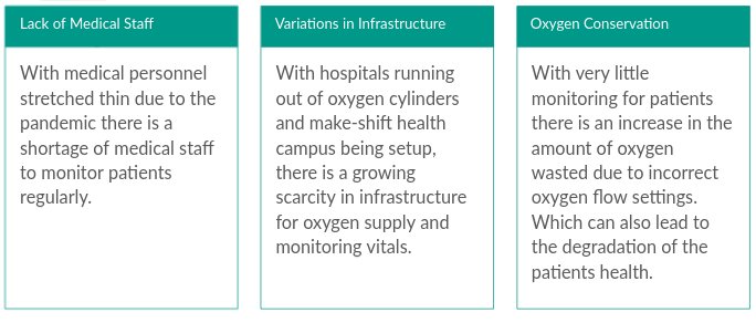
Problem Statement
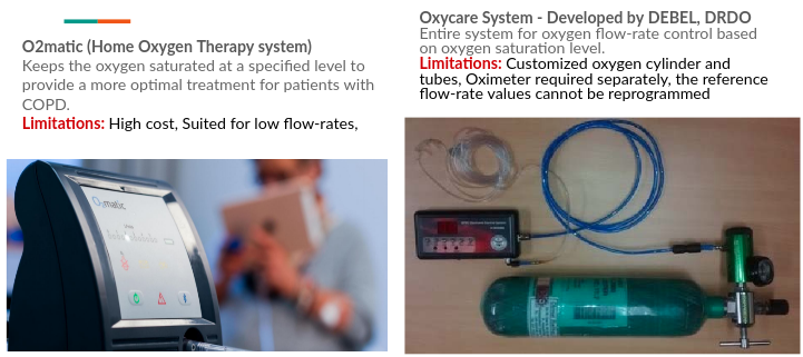
Existing Solutions
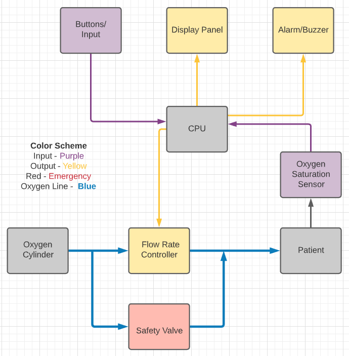
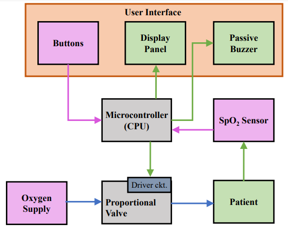
Design
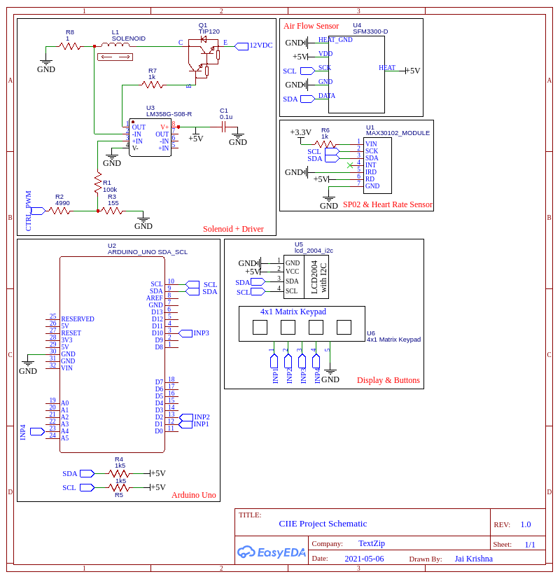
Schematic
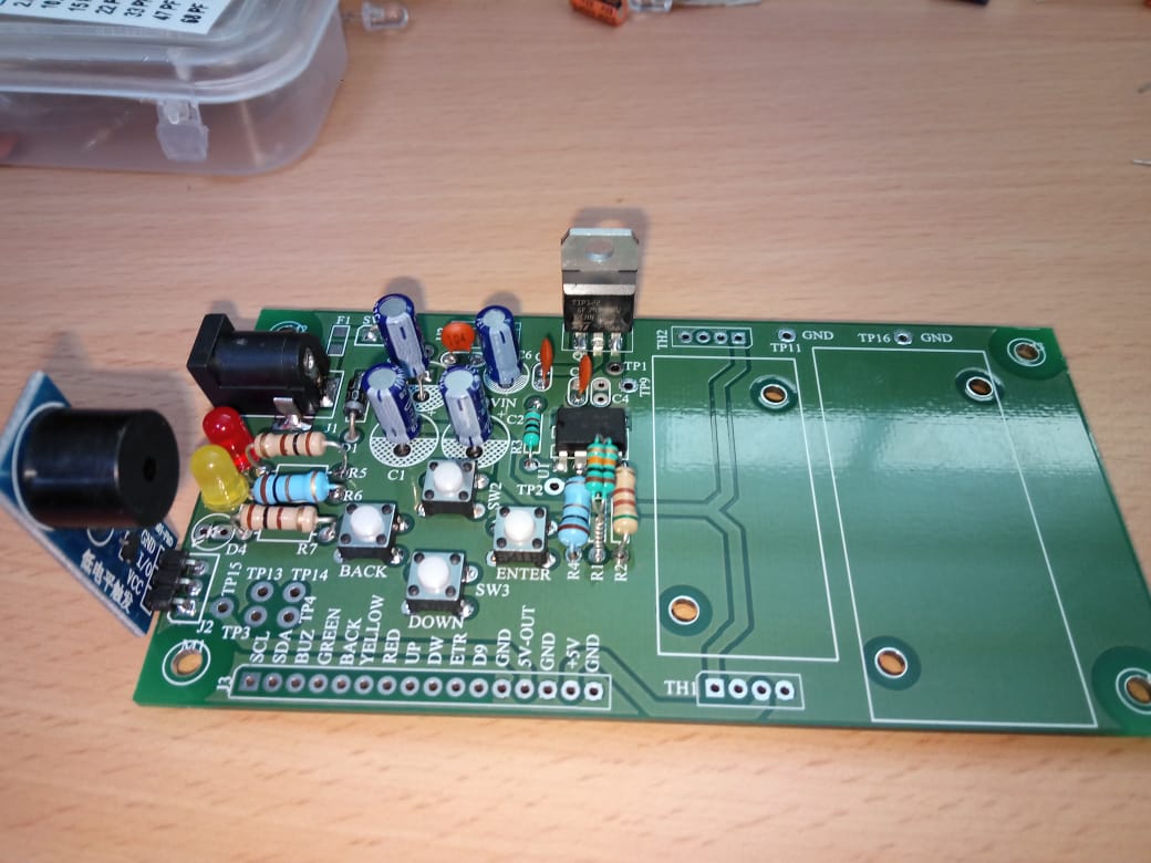
Hardware
Software
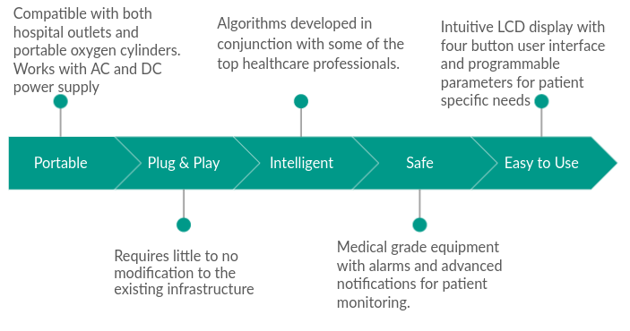
Features
Methodology
The device automatically regulates the oxygen flow rate supplied to the patient based on the current and past trends of the patient’s vitals(oxygen saturation levels). These vitals are sampled periodically through a discrete-time control algorithm that has been explained in the next section.
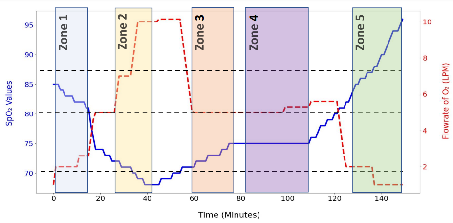
The discrete-time control algorithm consists of two parts, a state machine that determines the minimum and maximum oxygen flow rate provided to the patient based only on their current oxygen saturation levels, and an Integral-Derivative control loop that calculates the exact flow rate within the range prescribed by the state machine taking into account the past trends of the oxygen saturation levels.
The state machine divides the interval of flow rates from 2 LPM to 15 LPM (both inclusive) into four stages. Based on the current SpO2 reading of the patient, the state machine determines which stage to use to set the boundaries. The base flow rates for each stage are as tabulated below.
| Base No. | Min. $SPO_2$ % | Max. $SPO_2$ % | $Base_{LPM}$ |
|---|---|---|---|
| 1 | 87 | 99 | 1 |
| 2 | 80 | 87 | 2 |
| 3 | 70 | 80 | 5 |
| 4 | 0 | 70 | 10 |
The exact SpO2 readings are then processed using the formula given below:
\[Tot_{LPM} = min[(Base_{n}+I_{LPM}+D_{LPM}),Base_{n+1}]\]There are three parts to this formula:
Base $_{n}$ : The base flow rate of the $n$th base obtained from the state machine.
D $_{LPM}$ : A derivative term, which increases its value when a negative trend is observed in SpO2 readings.
I $_{LPM}$ : An integral term, which increases its value when a stationary trend is observed while the SpO2 readings are less than 90%.
\[\begin{equation} D_{LPM}=\left(\frac{|\Delta SpO_{2}(t)|}{|\Delta SpO_{2}(t)|+SpO_{2_{width}}(t)}\right)\times Base_{width} \end{equation}\\\]—
\(\begin{align} &\Delta SpO_{2}(m) = SpO_{2}(m) - SpO_{2} (m-1)\\ &Base_{width}(t)= B_{n}(m)-B_{n-1}(m)\\ &SpO_{2_{width}}(m)=(SpO_{2}(m)-\textrm{Min. $SpO_{2}$ of $B_{n}$}) \end{align}\)
Derivative Term:
When \(SPO_2(t-1) >SPO_2(t)\)
\[Base_{width} =CurrentBase_{LPM} - (Current-1)Base_{LPM}\] \[width = |\Delta SPO_2| + (SPO_2(t)-Min. SPO_2\ of\ Current Base)\] \[Derivative_{LPM}=\dfrac {|\Delta SPO2|} {width} Base_{width}\]When the SOP2 value is stationary for a considerable amount of time, a counter is initialized that is used by the $Intergral_{LPM}$ to update its value.
Integral Term:
When \(SPO_2(t-1) =SPO_2(t)\)
\[stationary_{counter} += 1\] \[Base_{width}=Current Base_{LPM} - (Current-1) Base_{LPM}\] \[Integral_{LPM}=Base_{width} (stationary_{counter}-1)/10\]These three terms are summed up, and a saturation operation is performed, capping the flow rate at the base flow rate of the next higher stage.
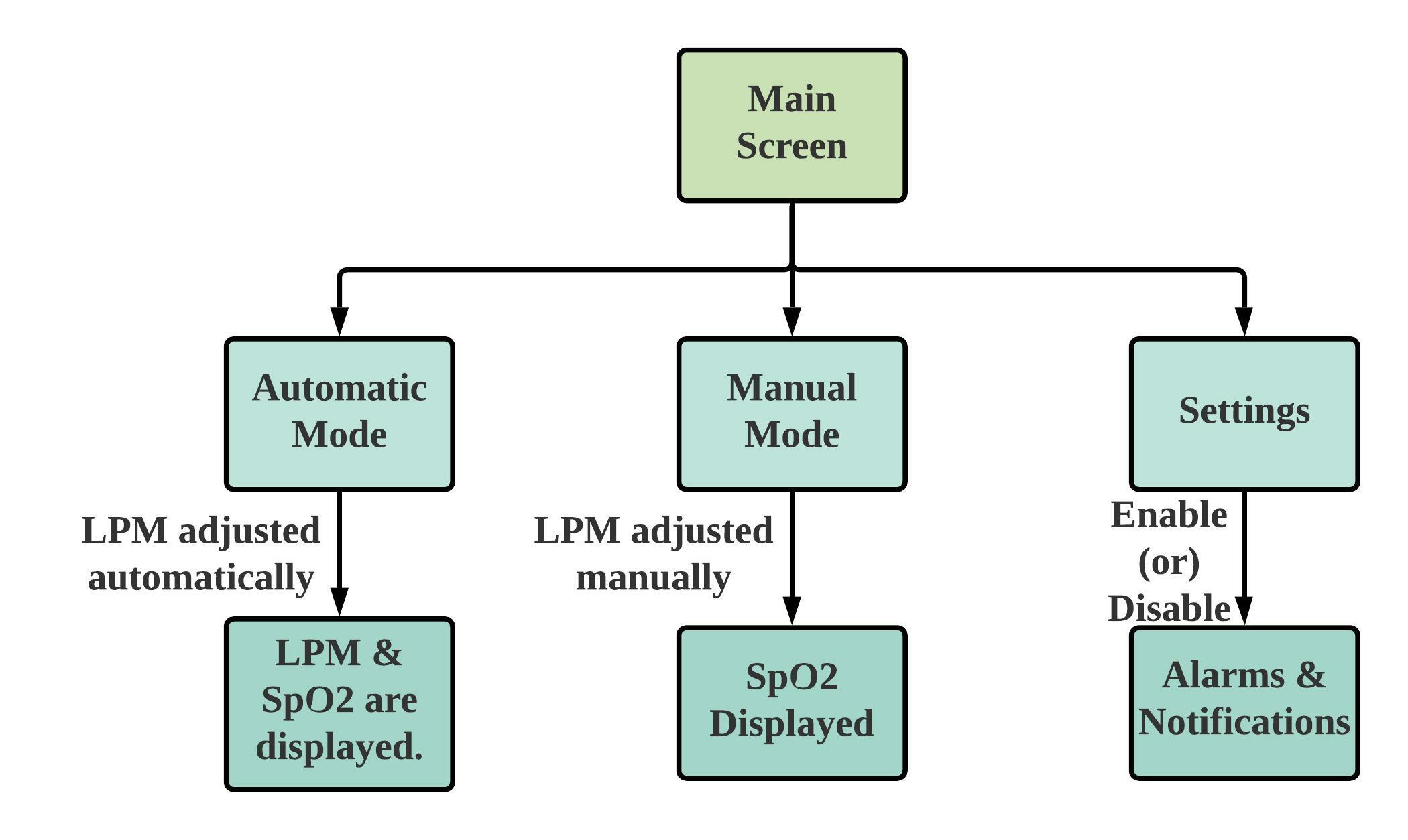
In this method, our device automatically adjusts the flow rate as required without any human supervision, thus helping avoid the wastage of precious O2 reserves. We have also provided a manual mode, using which the attendants or nurses can set the flow rate to a constant value and an option to vary the control algorithm parameters.
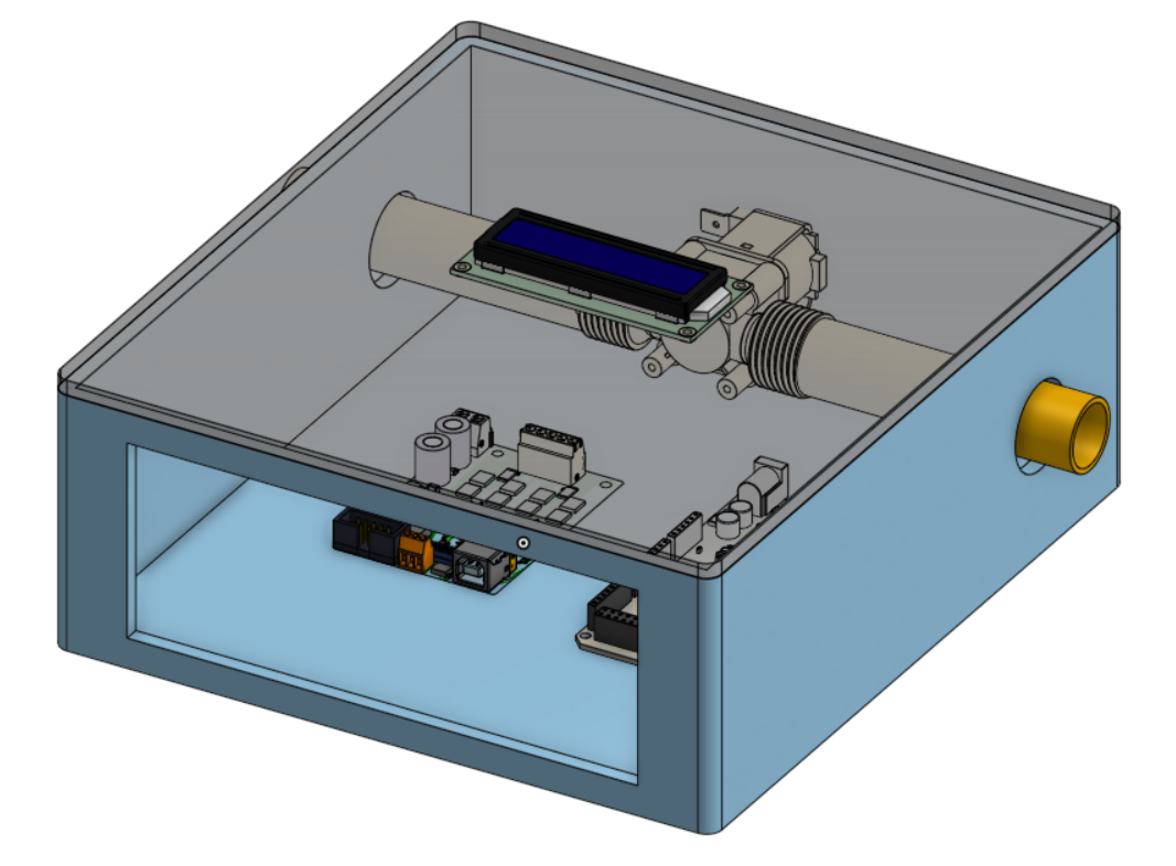
CAD Model
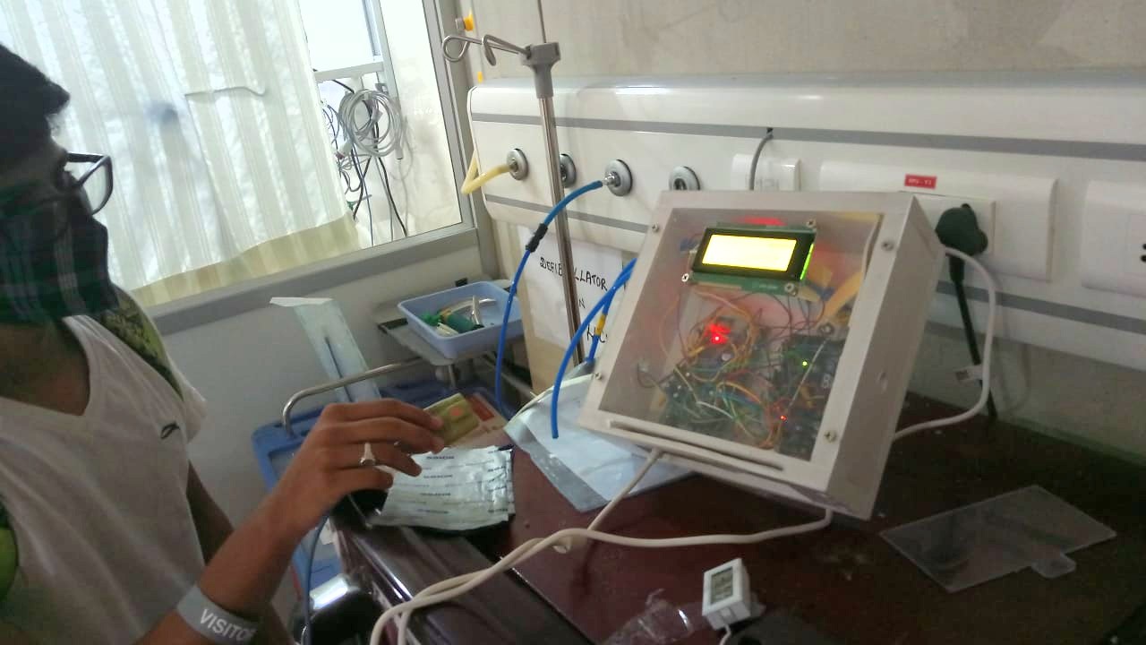
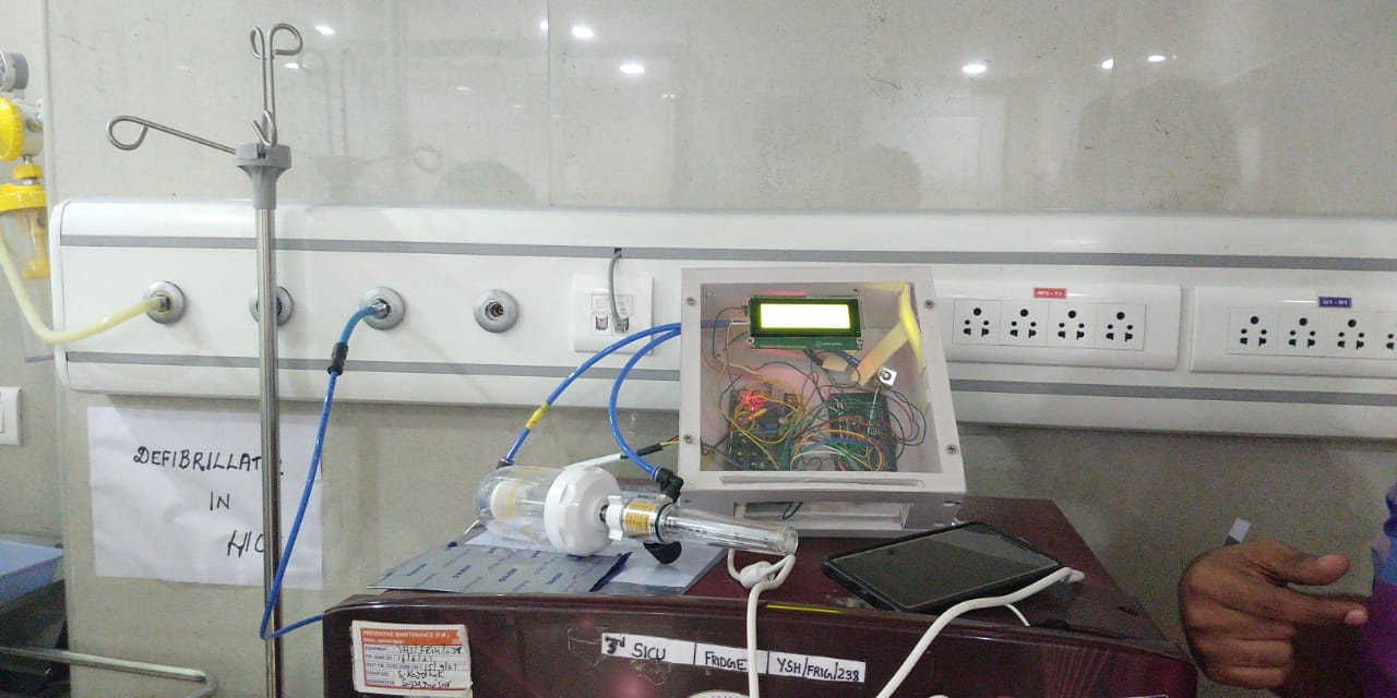
Clinical Testing