
The aim of this project is to “Design, Develop and Implement an Autonomous Stair Climbing Robot which can climb stairs, turn at the quarter-landings and deliver packages autonomously”.
Team
| Members | Sub-System |
|---|---|
| Bandi Jai Krishna | CAD, Simulation |
| Utkarsh Jain | Simulation, Electronics |
| Abijith Y.L. | CAD, Simulation |
| Sriram Kodey | CAD, Image Processing |
| T. Vamsi Krishna | Image Processing |
Introduction
In an e-commerce scenario, the last mile delivery is the phase where the customer experiences / receives his desired ordered item. Sophisticated handling and delivery of the product ensures customer confidence.
Robots can be used to assist the ‘Wishmasters’ in making deliveries ergonomic thus resulting in efficient delivery. This kind of automation can prove to be very helpful for delivery of large items such as refrigerators, Washing Machines etc. in multi-floor buildings where elevators aren’t available. They can also find applications in good movements within the warehouse.
This project will act as a prototype for the above-mentioned vision and will be a huge step towards the automatization of e-commerce deliveries.
Motivation
The motivation behind this project is to develop an autonomous stair climbing robot which will help improve Flipkart’s last-mile delivery’s speed and efficiency and subsequently increase the customer confidence in Flipkart.
Design Alternatives
In the designing process, during the ideation phase, several different options and mechanisms were explored. The merits and limitations of each mechanism were considered and three of the most suitable mechanisms were selected. These were modelled using Solidworks(CAD Modelling Software) and were simulated in the environment described in the problem statement. The results of these simulations were analysed and based on this analysis, the final mechanism/design was developed.
R-Hex
The first mechanism that was modelled and tested was based on the R - Hex project developed by DARPA. This mechanism has been specifically designed to travel on varying terrains. It was also tested for climbing stairs and the results were positive. Thus this mechanism was selected for testing.
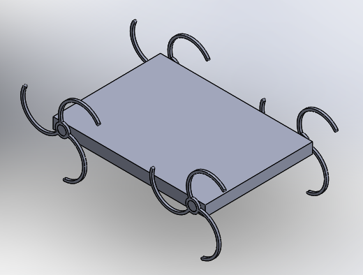
A design was developed, inspired by the R - Hex Project: it had a similar wheel geometry with more spokes to increase the effective contact with the ground and has four wheels. This design was simulated with the load and environment described in the problem statement and results were as follows:
The robot was able to climb stairs after some optimisation to the design and was also able to carry the necessary load. However, there was a lot of vibration and sudden shifts in the position of the centre of gravity of the package due to frequent slipping of the wheels on the stair edges. This is an undesirable trait and thus the model was discarded.
Curved Spokes Variation
Rocker Bogie
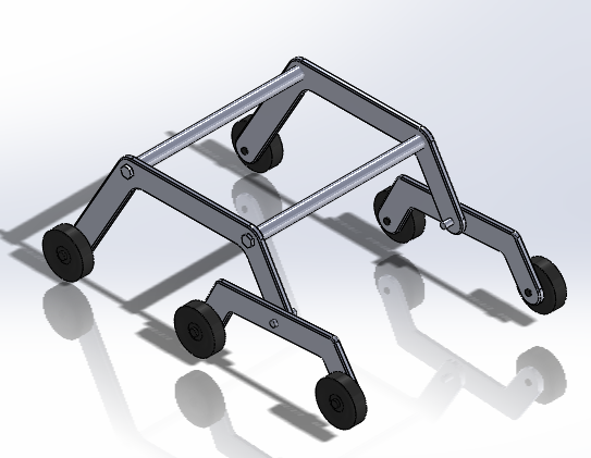
The second mechanism that was selected for testing was based on the Rocker Bogie Mechanism, first introduced by NASA in it’s Mars Rovers. The use of this mechanism would enable us to climb over an obstacle that is two times the size of the wheel diameter and this system would also act as a suspension without the use of springs or torsion beams. These traits encouraged us to consider it for testing.
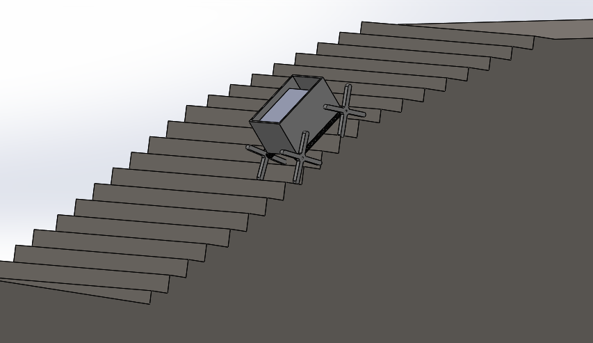
CAD models were made for several variations of this mechanism and simulated in the environment described in the research paper. The variations included independent and linked bogies, Dimensional changes in the links of the mechanism, Several pivot points and a modified version of the Bogie. All these modifications were made as an attempt to tune the mechanism to tackle varying step dimensions and increase traction, which is necessary to move the package up the stairs. Although the design developed after these modifications was capable of climbing stairs, it failed to do so in the presence of load, thus making it impractical to use it in the robot.
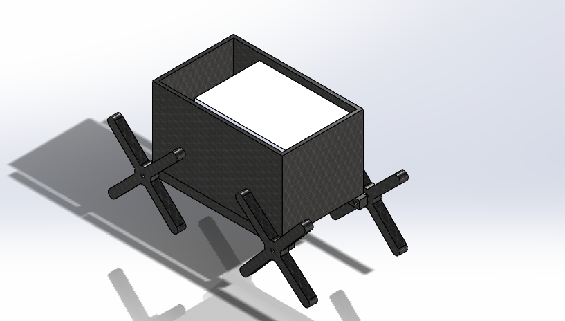
6 Wheel Version
 In Figure: 6 Wheel Rocker Bogie
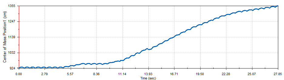
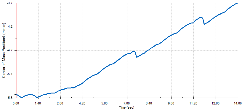
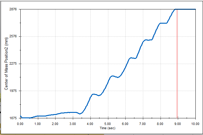 In figure: Center of mass position vs time graph for rocker-bogie based model
8 Wheel Version
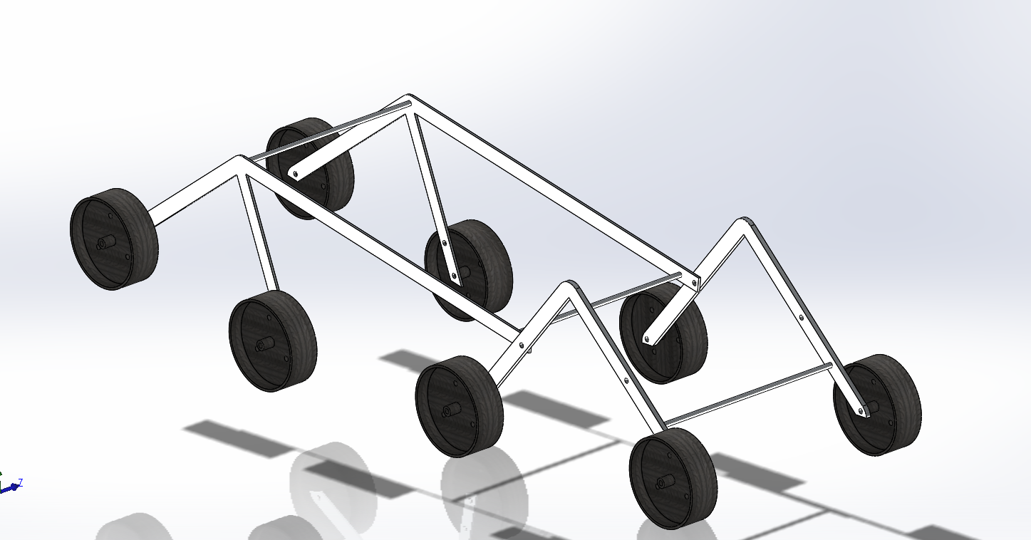 In Figure: 8 Wheel Rocker Bogie
Continuous Tracks
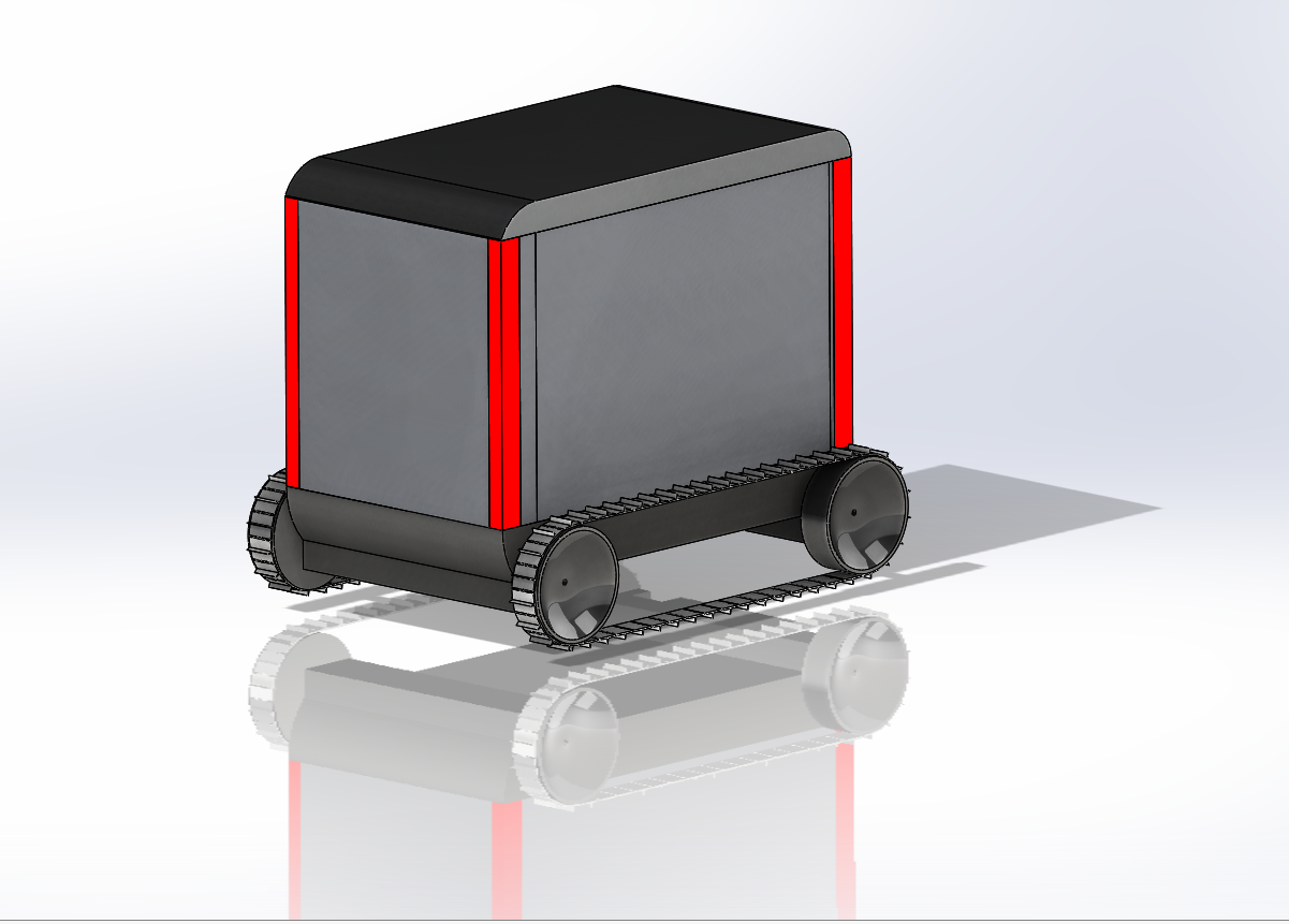
The third mechanism selected for testing is the Continuous Track. The concept can be dated back to the 1900’s and has proved to be a great solution for a propulsion system where high traction and grip is essential. Other positive traits being, better mobility (ability to perform spot turns), better performance in terms of providing a smoother climb. A couple of designs have been made in solidworks and then tested in Sketchup using the MsPhysics plugin. The results were satisfactory and thus convinced us to use this mechanism in the final bot.
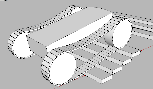 In figure: Continuous tracks model
Proposed Desgin
The proposed design uses the continuous track mechanism. To ensure the tilt stability of the bot, the centre of gravity must be low; to ensure this, we have the electronic components (motors, steppers and battery being the heavy parts) placed at a very low point. The robot need not shift modes to climb stairs, and can travel at relatively higher speed on the ground which decreases the overall time required for the robot to climb the stairs. We have two wheels on each side with a forward wheel drive system, this enables us to shift the center of gravity forward helping us to prevent toppling during the climb manoeuvre. We also will be able to perform spot turns, helping us to change the direction of the robot on the quarter landing. We have a retractable arm system at the rear end of the robot which doubles as an emergency brake and as a system which helps the robot to align itself with the slope of the stairs at the beginning of the descent.
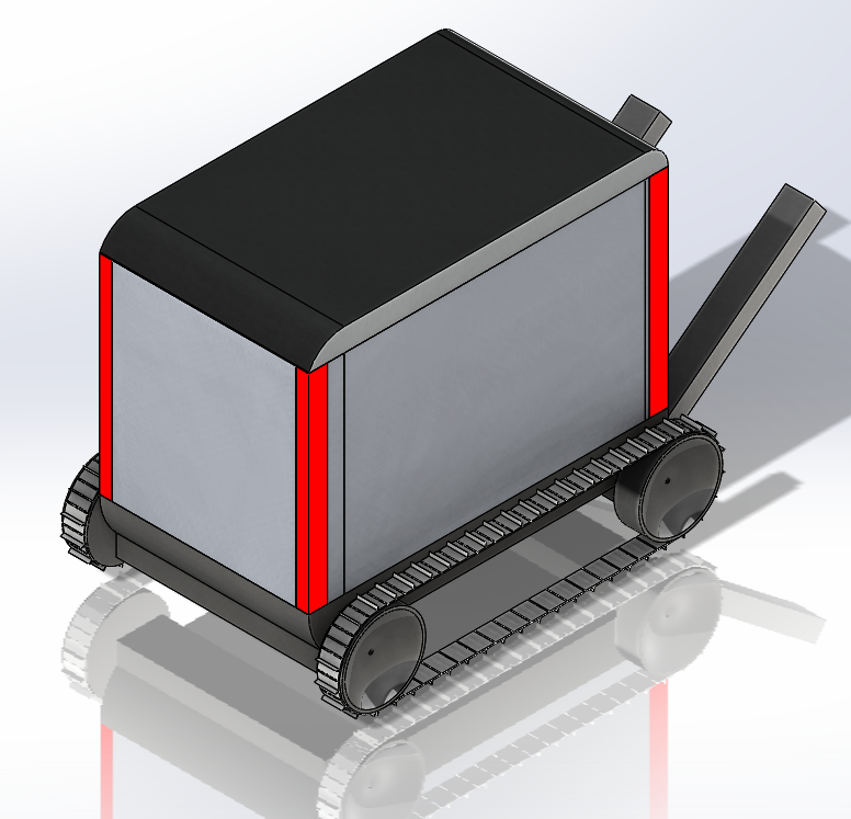
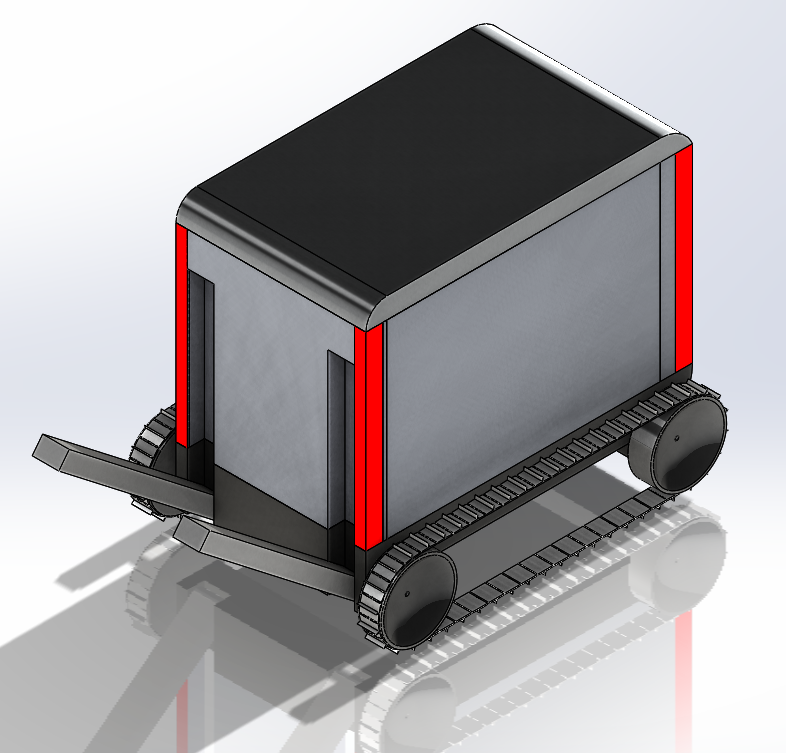
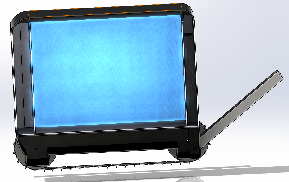
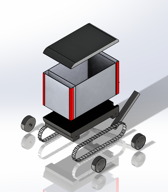
The entire robot has been divided into four different parts :- The electronics compartment, The package compartment and the secondary electronics compartments at the front and rear ends of the bot. The electronics compartment houses the heaviest parts, adding to the stability of the bot. The package compartment is bigger than the maximum package dimensions, this was done to add cushioning inside the package compartment to ensure the safety of the package. The electronics compartments at the front and rear will house the camera for the stair detection and IR Distance sensors for obstacle detection.
Technical & Hardware Architecture
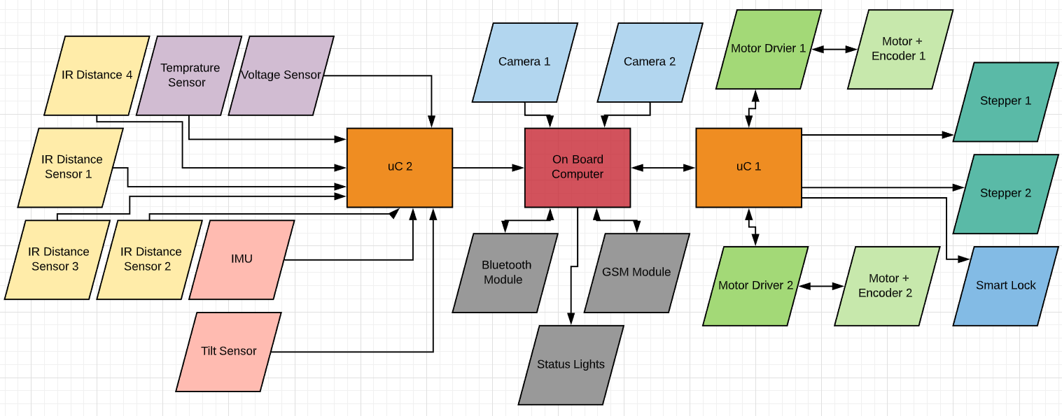 In figure: Complete Hardware architecture
The above flowchart represents the internal architecture of the robot. Enabled with two seperate microcontrollers for input collection and output distribution, the OBC is used to run complex image processing algorithms from the camera stream data and act as a bridge between the two microcontrollers. The above architecture has been chosen to keep the entire design modular.
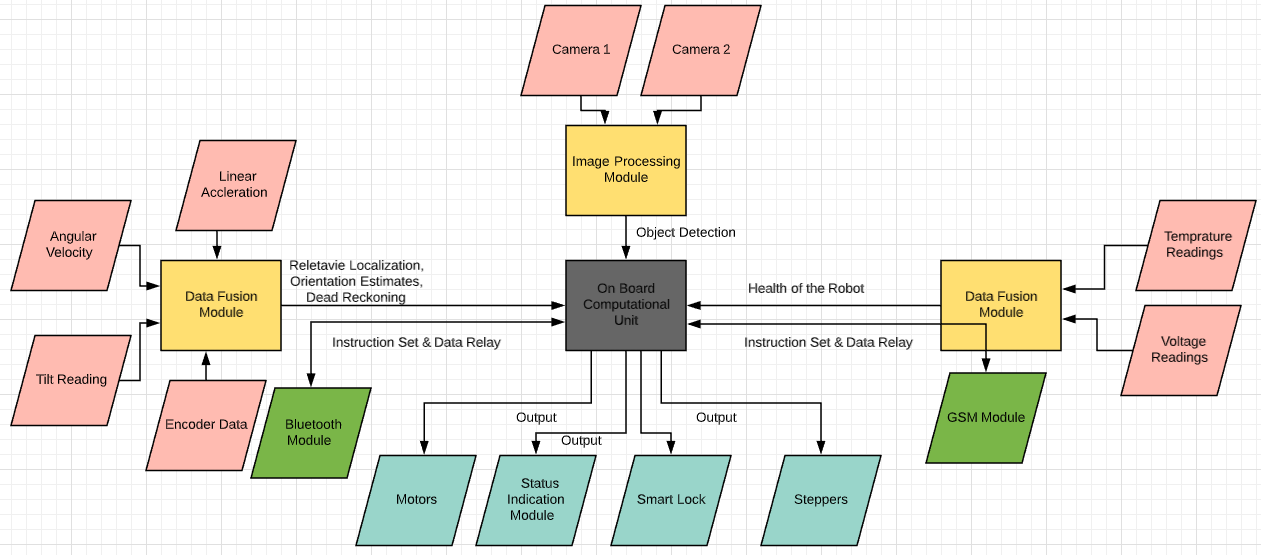 In figure: Complete Software Architecture
IR Distance Sensor
An IR distance sensor uses a beam of infrared light reflected off an object to measure its distance. The distance is calculated using triangulation of the beam of light. The sensor consists of an IR LED and a light detector or PSD (Position Sensing Device).
When the beam of light gets reflected by an object, it reaches the light detector and an ‘optical spot’ forms on the PSD. The sensor has a built-in signal processing circuit. This circuit processes the position of the optical spot on the PSD to determine the position (distance) of the reflective object. It outputs an analog signal which depends on the position of the object in front of the sensor.
Non-Linear Responce Curves
IR distance sensors output an analog signal, which changes depending on the distance between the sensor and an object. A generic analog IR sensor gives out analog readings of about 2.5 V when an object is 100 cm away to 1.4 V when an object is 500 cm away. The graph also shows why the usable detection range starts at 100 cm. Notice that the output voltage of an object that is 30 cm away is the same as the output voltage for an object that is 160 cm away. The usable detection range therefore starts after the peak at roughly 100 cm or 2.5 V.
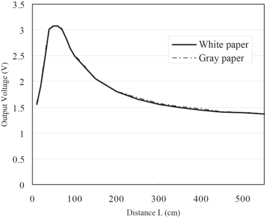 In figure: Output voltage vs distance
The output voltage when plotted against the inverse of the distance results in a linear plot for distances greater than 100cm.
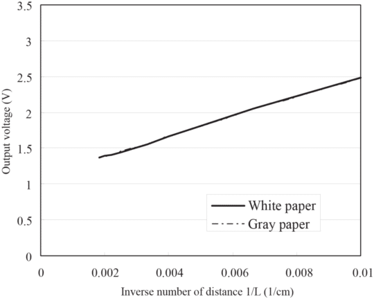 In figure: Output voltage vs inverse number of distance
The linear function for the above graph is represented by the equation:
\[y = 137500x + 1125\]With $y$ equal to the output voltage in mV and $x$ equal to 1/distance in cm. This results in the following formula for the distance between the sensor and an object:
\[Distance (cm) = 1/((Output_voltage_mV – 1125)/137500)\]This function is based on data from the datasheets of SHARP IR Sensor. The output characteristics of the sensor will vary slightly from sensor to sensor so you might get inaccurate readings.
Bluetooth Module
The Bluetooth module is used to create a Bluetooth Network consisting of a Personal Area Network or a piconet which contains a minimum of 2 to maximum of 8 bluetooth peer devices- Usually a single master and upto 7 slaves. A master is the device which initiates communication with other devices. The master device governs the communications link and traffic between itself and the slave devices associated with it. A slave device is the device that responds to the master device. Slave devices are required to synchronize their transmit/receive timing with that of the masters. In addition, transmissions by slave devices are governed by the master device (i.e., the master device dictates when a slave device may transmit). Specifically, a slave may only begin its transmissions in a time slot immediately following the time slot in which it was addressed by the master, or in a time slot explicitly reserved for use by the slave device.
Data transfer is achieved through embedded low cost transceivers. Bluetooth works on the frequency band of 2.45GHz and can support upto 721KBps along with three voice channels.
Stepper Motor
Stepper motors are DC motors that move in discrete steps. They have multiple coils that are organized in groups called “phases”. By energizing each phase in sequence, the motor will rotate, one step at a time. With a computer controlled stepping you can achieve very precise positioning and/or speed control. For this reason, stepper motors are the motor of choice for many precision motion control applications.
Features of Stepper Motor
Positioning : Since steppers move in precise repeatable steps, they excel in applications requiring precise positioning such as 3D printers, CNC, Camera platforms and X,Y Plotters. Some disk drives also use stepper motors to position the read/write head. Speed Control : Precise increments of movement also allow for excellent control of rotational speed for process automation and robotics. Low Speed Torque : Normal DC motors don’t have very much torque at low speeds. A Stepper motor has maximum torque at low speeds, so they are a good choice for applications requiring low speed with high precision.
Torque/ Speed characteristics
One weakness with the SM is its limited torque abilities at high speeds, since the torque of a SM will fall with rising speed above the cutoff speed (i.e. in resonant speed) , as shown in figure below. When the motor is operating below its cutoff speed, the rise and fall times of the current through the motor windings occupy an insignificant fraction of each step, while at the cutoff speed, the step duration is comparable to the sum of the rise and fall times.
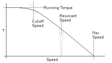 In figure: Torque vs speed
Step Angle of the SM
The angle through which the motor shaft revolves for each command signal is named the step angle (β) as shown in figure below. Reduced the step angle, increased the number of steps per revolution and higher the resolution or accuracy of positioning obtained. The step angles can be as slight as 0.72º or as large as 90º. But the most traditional step sizes are 1.8º, 2.5º, 7.5º and 15º.
Types of SMs According to Arrangement of Stator Windings
The stator part of the Stepper Motor holds numerous windings. The arrangement of these windings is the major factor that differentiates various kinds of SMs from an electrical point of opinion. Thus SMs may be wound using either unipolar windings or bipolar windings and as follows.
Unipolar Motors
The unipolar stepper motor operates with one winding with a center tap per phase. Each section of the winding is switched on for each direction of the magnetic field. Each winding is made relatively simple with the commutation circuit, this is done since the arrangement has a magnetic pole which can be reversed without switching the direction of the current.
Bipolar Motors
With bipolar stepper motors, there is only a single winding per phase. The driving circuit needs to be more complicated to reverse the magnetic pole, this is done to reverse the current in the winding. This is done with an H-bridge arrangement, however, there are several driver chips that can be purchased to make this a more simple task. Unlike the unipolar stepper motor, the bipolar stepper motor has two leads per phase, neither of which are common. Static friction effects do happen with an H-bridge with certain drive topologies, however, this can be reduced by dithering the stepper motor signal at a higher frequency.
DC Motors
A DC motor is any of a class of rotary electrical motors that converts direct current electrical energy into mechanical energy. The most common types rely on the forces produced by magnetic fields. Nearly all types of DC motors have some internal mechanism, either electromechanical or electronic, to periodically change the direction of current in part of the motor. The main advantages of DC motors are:
- DC motors provide a fine control of the speed which can not be attained by AC motors.
- DC motors can develop rated torque at all speeds from standstill to rated speed.
- Developed torque at standstill is many times greater than the torque developed by an AC motor of equal power and speed rating.
High Torque geared motors
To generate high torques using a given motor, an assembly of gears is used. A gear’s transmission torque changes as it increases or decreases speed. Generally, by reducing the speed, a small torque at the input side is transmitted as a larger torque at the output side. The characteristic curves of a given motor are charts that enable us to determine the torque output at a specific speed.
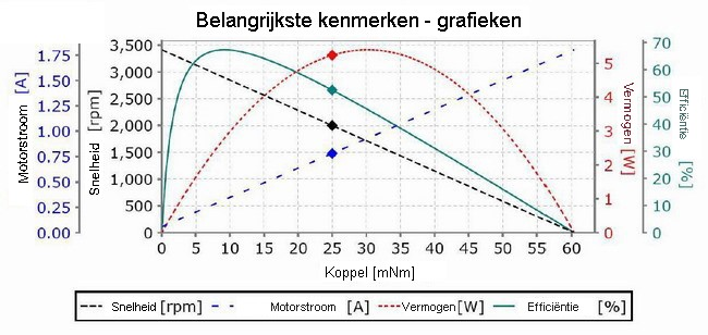 In figure: Main features - charts
To illustrate, for the motor in the figure above, delivering a torque of 25 mNm, the corresponding speed is 2000 rpm, at which the motor draws approximately 0.76A of current. This chart also tells us that this torque, speed and power are not optimum values for this type of motor. This is because the nominal (i.e. optimum) values apply when the motor is running at more or less maximum efficiency. However, because in practice the duty point of the motor will not always coincide with these values, the efficiency will be lower at that point, such that in practice the motors will often run hotter than expected.
It is important to consider all the characteristics while choosing a motor for a particular application.
Motor drivers
Motor drivers act as an interface between the motors and the control circuits. Motors require a high amount of current whereas the controller circuit works on low current signals. So the function of motor drivers is to take a low-current control signal and then turn it into a higher-current signal that can drive a motor. They consist of integrated H- bridge circuits, which are used to change the direction of rotation of the connected motors.
Encoders
An encoder is an electromechanical device that provides an electrical signal that is used for speed and/or position control. Encoders turn mechanical motion into an electrical signal that is used by the control system to monitor specific parameters of the application and make adjustments if necessary to maintain the machine operating as desired. The parameters monitored are determined by the type of application and can include speed, distance, RPM, position among others. Applications that utilize encoders or other sensors to control specific parameters are often referred to as closed-loop feedback or closed-loop control systems.
The application in which the motor encoder is being utilized will determine the motor encoder technology that needs to be used. The two broad types of motor encoder technologies available are:
Absolute Encoders: The output of an absolute motor encoder indicates both the motion and the position of the motor shaft. Absolute motor encoders are most often used on Servo Motors in applications where position accuracy is required.
Incremental Encoders: Incremental encoders provide a specific number of equally spaced pulses per revolution (PPR) or per inch or millimeter of linear motion. Incremental encoders consist of three basic components: a slotted disc, a light source and a dual light detector, as shown in Figure 6. The light source shines on the disc, which has a regularly spaced radial pattern of transmissive and reflective elements, called encoder increments. The quadrature light detector measures the amount of light passed through the slotted disc and generates two quadrature output pulse signals, denoted by A and B.
For the application of feedback control to motion systems with optical incremental encoders, the position is generally measured at a fixed sampling frequency. The measurement accuracy is limited by the quantization of the encoder, i.e., by the number of slits on the encoder disc. The quantization errors can be reduced by either using more expensive encoders with more increments or by using smart signal processing techniques. Furthermore, the position information of the encoders is distorted by several encoder imperfections, such as eccentricity and tilt of the disc, misalignment of the light detector/source, and a non-equidistant slit distribution.
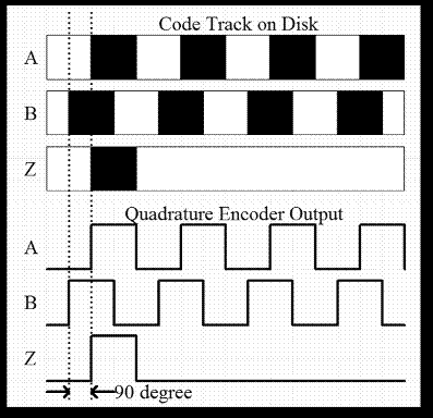 In figure: Output pulses given by incremental encoders
The quadrature incremental signals are typically decoded to obtain up to four times the base pulses per revolution (PPR). Quadrature decoding counts both the rising and falling edges of Channel A and B.
Encoder pulses during a sampling interval can be converted to motor speed using the equation: \(Cm = π* Dn / (n*Ce)\) where, Cm = conversion factor that translates encoder pulses into linear wheel displacement Dn = nominal wheel diameter (in mm) Ce = encoder resolution (in pulses per revolution) n = gear ratio of the reduction gear between the motor (where the encoder is attached) and the drive wheel
IMU
The term IMU stands for “Inertial Measurement Unit,” and is used to describe a collection of measurement tools. When installed in a device, these tools can capture data about the device’s movement. IMUs contain sensors such as accelerometers, gyroscopes, and magnetometers. IMUs combine input from several different sensor types in order to accurately output movement. The primary goal of an IMU is to track the 3D position and orientation of a rigid body in time without using any external references. For example, if the body begins at rest, the accelerometer can use the gravitational field to determine the orientation of the body. There is no way for an IMU to determine the initial x-y-z position of the body,2 so only relative motion can be estimated. When the body begins to move, it must experience either linear accelerations, angular velocities, or both. Angular velocity can be numerically integrated by microcontroller software to estimate the orientation of the body, and linear accelerations can be integrated to get linear velocities and again to get the net position change from the initial position. Sophisticated software integrators exist; they typically employ extended Kalman filters.
Because of sensor errors and errors due to numerical integration, estimates of linear velocity and position tend to accumulate error over time. These errors can be mitigated by occasionally referencing an external reference such as GPS. IMUs allow systems that rely on GPS to continue functioning when GPS is briefly unavailable.
An IMU can consist of a PCB with separate accelerometer and gyro ICs; a single IC incorporating both an accelerometer and a gyro; or a complete integrated solution, including onboard estimation software. An example IMU is the STMicroelectronics ASM330LXH, which features a three-axis accelerometer with a user-selectable full scale between ± 2g and ± 16g and a three-axis gyro with a user-selectable full scale between ± 125 and ± 2000 degrees/s. It communicates by I2C or SPI.
Data fusion algorithms
In terms of Inertial Measurement Unit (IMU) data fusion algorithm, the complementary filter and Kalman filter are the most widely used algorithms. Each has its unique advantages and disadvantages.
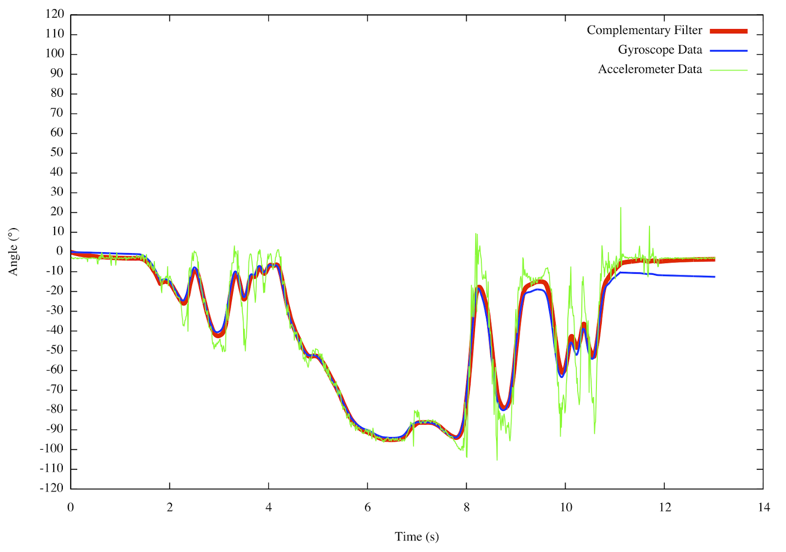
Complementary filter
The complementary filter consists of both low and high pass filters and as it is easier to implement this filter was implemented for getting precise data. In the Inertial Measurement Unit (IMU) accelerometer, gyroscope and magnetometer are integrated. Accelerometer and the gyroscope are the main sensor and the magnetometer is the correction sensor. All the forces working on the object are measured by an accelerometer and as the small forces create disturbance in measurement, long term measurement is reliable. So for the accelerometer, a low pass filter is needed for correction. In the gyroscopic sensor the integration is done over a period of time the value starts to drift in the long term, so a high pass filter is needed for gyroscopic data correction.
 In figure: Output pulses given by incremental encoders
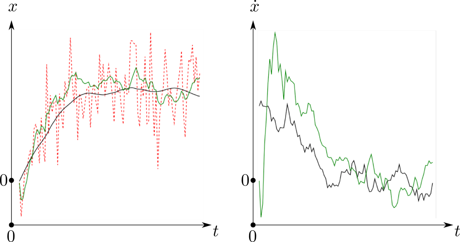
Kalman filter
For a dynamic system by predicting the future value from the previous data the situation of the system can be guessed. For this type of system which is continuously changing the Kalman filter is the perfect to make an educated guess of what happened. As this filter predicts the future from previous data so some initial value is considered in the beginning. In this implementation the filter starts working after the IMU is on and measures the initial value. Then the value is transmitted to the filter and thus the filter starts computing. Kalman filter uses correlation between prediction and what actually happened to make the prediction error.
 In figure: Output pulses given by incremental encoders
Temperature Sensor
Temperature sensors can be classified into two types based on their calibration methods. The output voltage can be linearly proportional to the Centigrade temperature or the Kelvin Scale. The devices that use the Centigrade Scale for calibration have an advantage over linear temperature sensors calibrated in Kelvin, as the user is not required to subtract a large constant voltage from the output to obtain convenient Centigrade scaling. Further, most Centigrade based temperature sensors don’t need external calibration or trimming to provide typical accuracies of ±¼°C at room temperature and ±¾°C over a full −55°C to 150°C temperature range. Most of the Integrated Circuits based temperature sensors use a delta-V BE architecture. The temperature-sensing element is then buffered by an amplifier and provided to the VOUT pin.
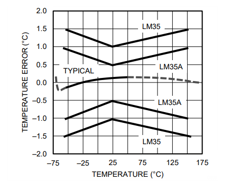
Transfer Functions & Error
The accuracy specifications for a Temperature sensor can be calculated with a simple linear transfer function: \(V_{OUT} = 10 mv/°C × T\) where • $V_{OUT}$ is the LM35 output voltage • $T$ is the temperature in °C Below attached is a comparison graph between the actual temperature and the error in the readings taken using a variety of temperature sensors.
 In figure: Output pulses given by incremental encoders
DC Voltage Sensor
Most of the voltage sensors use a resistor divider circuit consisting of a sensor and a reference resistor which is used to measure the scaled down voltage. The voltage that is developed across the reference resistor or sensor is buffered and then given to the ADC. The output voltage of the sensor can be expressed as
\[V_{out} = \dfrac{R_{M}}{R_{M}+R_{F}}V_{ref}\]One major drawback of the above method is the amplification of the voltage across both the sensor and the reference resistor by the amplifier. The voltage changes due to the change in resistance of the sensor can be isolated and amplified using a resistance bridge.
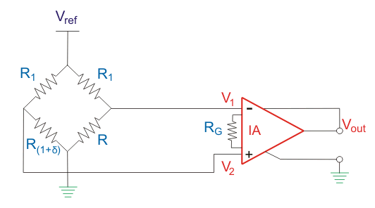 In figure: Internal circuit of a DC voltage sensor
The output voltage can be calculated using the following formula:
\[V_{out} = \dfrac{R_{M}\delta}{R_{M}+R_{F}(1+(R/R)(1+\delta))}V_{ref}A\]Camera Modules
Most Camera Modules come with parallel & MIPI interfaces. CMOS camera modules will be effective in any application or environment because of their versatility and wide range of options to choose from. Embedded camera modules can be interfaced to various processors likeNXP IMX8, IMX7, IMX6 & NVIDIA’s Jetson Nano, Xavier and TX2, Google Coral Dev Board, Rockchip RK960 Board and TI’ DM3730. The light collected by the object through the lens is converted into an electrical signal by a CMOS or CCD integrated circuit, and then converted into a digital image signal by an internal image processor (ISP) to be output to a digital signal which is then processed by the on board computer to filter out the required components from the images captured.
On-Board-Computer
The on-board computer (OBC) is the component of the robot which acts as the ‘brain’. It has a similar function as the CPU in a personal computer. It takes input from various electronic components and gives output to various others.
The architecture of our robot makes the OBC take direct input from two camera modules, a Bluetooth module and a gsm module. It also takes indirect input (through a microcontroller) from four IR distance sensors, a temperature sensor, a voltage sensor, an IMU and a tilt sensor.
Similarly, the OBC is also responsible for giving output instructions to the status lights module, and the microcontroller which is controlling the motors and steppers. The OBC takes in input from the cameras and processes the frames to detect stairs (during normal operation) and to detect the wishmaster (during the Follow-the-wishmaster mode). Additionally, the OBC uses the readings from the IR distance sensors to detect obstacles and directs the output microcontroller to do the necessary. The information from the temperature and voltage sensors is used by the OBC to determine the overall health of the power systems and is sent to the wishmaster’s app and the central server through the bluetooth and gsm modules respectively.
Microcontrollers
A single-board microcontroller is a microcontroller built onto a single printed circuit board. This board provides all of the circuitry necessary for a useful control task: a microprocessor, I/O circuits, a clock generator, RAM, stored program memory and any necessary support ICs.
The robot houses two microcontroller boards. One of them is used to take inputs from various sensors like IR distance sensors, voltage sensor, temperature sensor, tilt sensor and the IMU. It takes input through the GPIO pins and passes the data onto the OBC which decides what to do with the above information.
After the OBC processes the information, it passes instructions to the microcontroller which controls the output. This microcontroller is responsible for controlling the motor drivers which in turn, command the motors. The stepper motors used to control the ‘emergency braking arms’ are also commanded by this microcontroller. Finally, the output microcontroller also controls the smart lock system.
NeoPixel Strips
The WS2812 Integrated Light Source — or NeoPixel in Adafruit parlance — is the latest advance in the quest for a simple, scalable and affordable full-color LED. Red, green and blue LEDs are integrated alongside a driver chip into a tiny surface-mount package controlled through a single wire. Each individual NeoPixel draws up to 60 milliamps at maximum brightness white (red + green + blue). In actual use though, it’s rare for all pixels to be turned on that way. When mixing colors and displaying animations, the current draw will be much less.
Features & Add-ons
Our current design is very simplistic and allows us to add various out-of-the-box features. The following is a list of features that are currently planned for the proposed design. This list is not exhaustive and may be expanded in the future.
IoT based Data Logging Module
The robot is equipped with a GSM module that lets it access the internet and relay back data like position, health of the vehicle and other crucial information to a central server that can be used to monitor the robot and command it in case of emergencies in real time. The feature is extremely useful when the number of robots in the warehouse or for delivery are scaled up.
Manual Control Mode
The “Manual Control Mode” enables the wishmaster to control the robot from their smartphone. This lets the wishmaster help the robot do complex maneuvers like crossing roads, moving around obstacles quickly and efficiently if the need be.
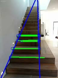
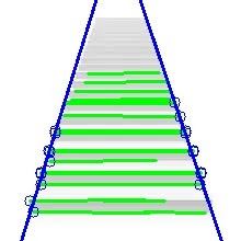
Stair Detection Module
The feed from the camera is taken and processed frame by frame using various image processing techniques such as thresholding, masking, conversion to binary, eroding and dilating the image to finally filter out the endpoints of each of the stairs. The robot will then use these to align itself with the center of the staircase while making the climb or descending.

Status Indication Module
NeoPixel strips have been placed at the 4 corners of the robot. This enables the robot to visually communicate with people in its vicinity. The status indication module is used to send out visual signals to help people around the robot respond appropriately when interacting with the robot. A few important cases where there visual signals can be used include manoeuvring mechanisms like turnings, low battery, or other pre-programmable scenarios like securement of the package lock, and physical damage to the robot.
Follow Wishmaster Mode
Our robot also has a special mode called the ‘Follow wishmaster’ mode. When this mode is activated by the wishmaster (using the app), the robot will automatically start to follow the wishmaster( who will be standing in front of the robot) using its camera modules. This will be accomplished by using the computer vision technique called ‘Haar classifiers (for person detection)’. The robot will also be programmed such that it never collides into the wishmaster or any other obstacle during this operation (using the IR distance sensors).
Smart Lock Module
The package to be carried on the robot, will be loaded into a package container. The package container is a partition in the body of the robot which will be secured using the smart lock system. The smart lock system is a solenoid valve powered lock. It will be controlled by the wishmaster using the bluetooth enabled app (which is also used to control the robot in the manual mode). The solenoid lock denotes a latch for electrical locking and unlocking. It is available in ‘unlocking in the power-on mode’ type, and ‘locking and keeping in the power-on mode’ type, which can be used selectively for situations. The power-on unlocking type enables unlocking only while the solenoid is powered on. A door with this type is locked and not opened in case of power failure or wire disconnection, ensuring excellent safety. Hence, we will be using the ‘unlocking in power on mode’ type lock.
Emergency Braking System
In the event of an emergency, like power failure, the robot might be stranded in the middle of a flight of stairs. To tackle this problem we have installed this emergency braking system. When the robot detects that the battery is going to die, it will automatically go into a low power mode where the remaining power is used to send the details of the problem along with the location of the robot to the central server. This contingency power is also used to lower the arms powered by the stepper motors towards the downward slope of the stairs so that in the event of the robot slipping, the arms will stop it from going further down and provide support to stay there until help arrives. The arms will have a rubber stopper with high grip at their ends to maximise the safety of the robot.
Kill Switch
The kill switch is a safety mechanism used to shut off the robot in the event of an emergency. Unlike a normal shut-down switch or shut-down procedure, which shuts down all systems in order and turns off the machine without damage, a kill switch is designed and configured to abort the operation as quickly as possible (even if it damages the equipment) and to be operated simply and quickly, so that even a panicked operator with impaired executive functions or a by-stander can activate it. The switch will be installed on the robot in a manner which will make it easily noticeable and operable.
Obstacle Detection
Obstacle detection is a very important feature of our robot. This will help the robot to avoid colliding with the various obstacles present in its environment. We will be using four IR distance sensors (one on each side of the robot) to measure its distance from the nearby obstacles. If the reading from any of the sensors goes below a particular safety threshold, the robot will stop moving. This will be useful for the robot to avoid damage to itself as well as other things, both living and nonliving.