
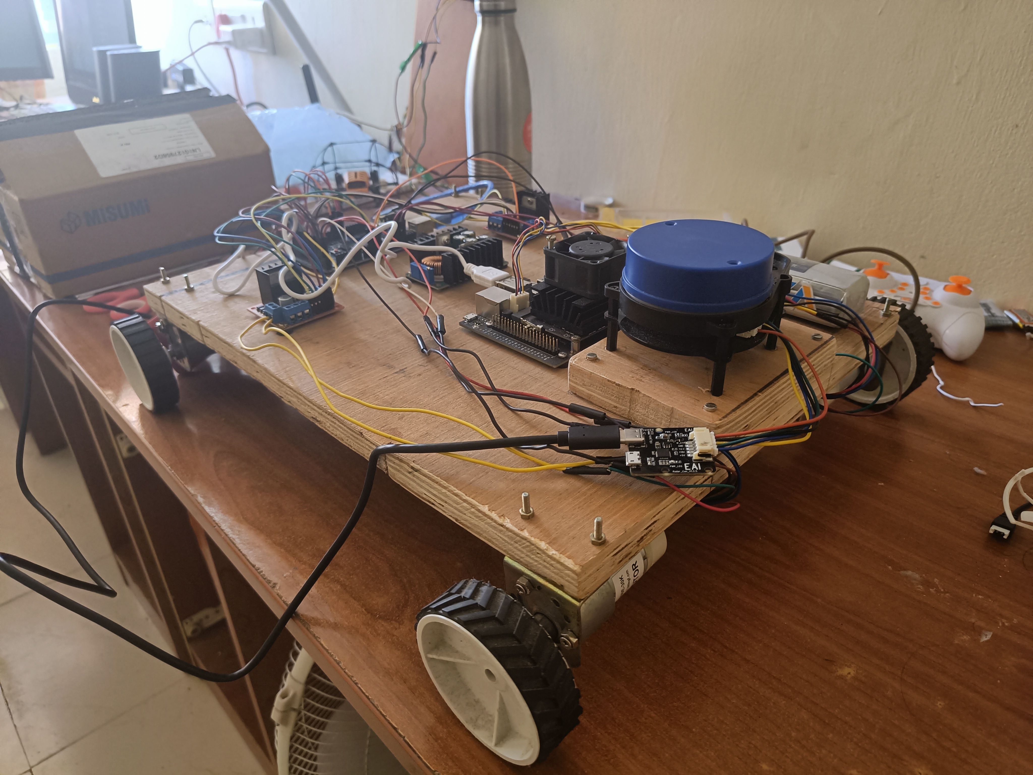
An Autonomous Ground Vechile for exploring concepts like localization, path planning, control in ROS.
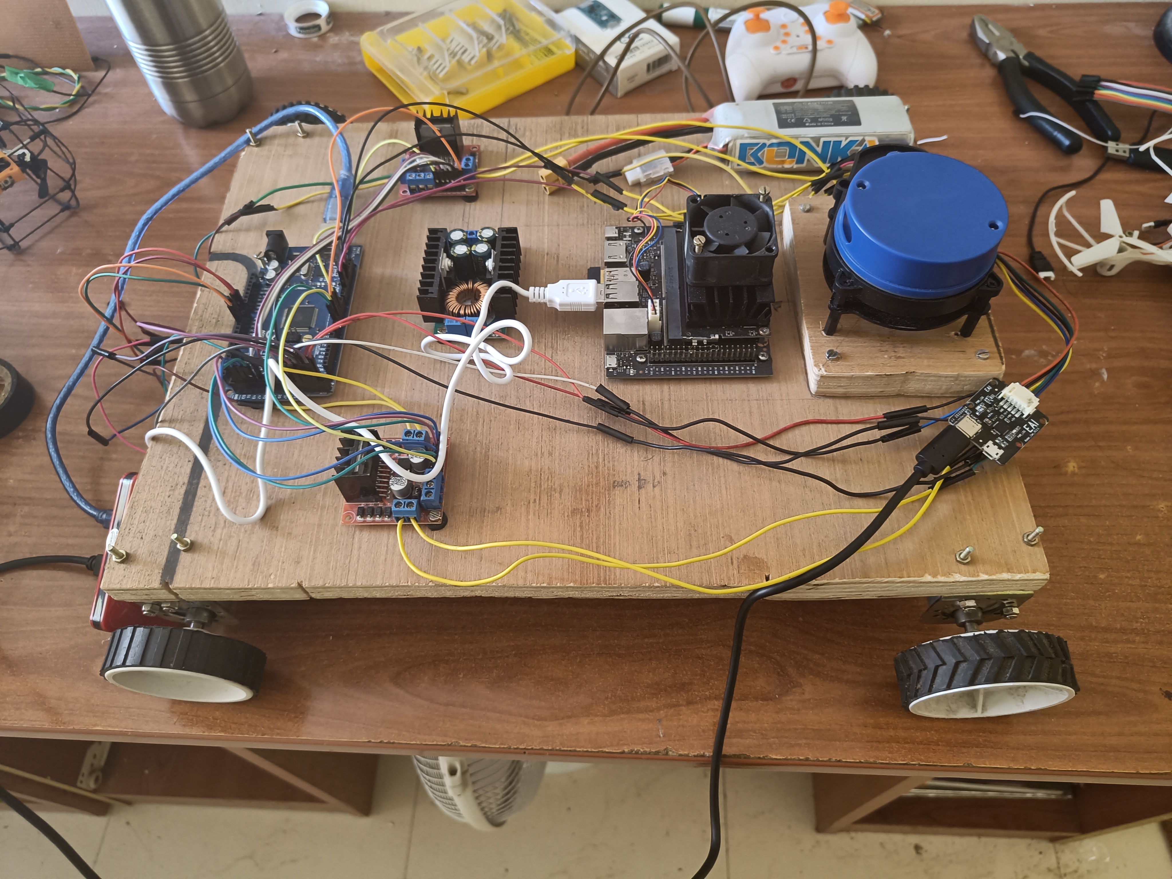
Hardware
- NVIDIA Jetson Nano
- Arduino Mega
- Buck Converter
- RPLIDAR A8
- L298N Motor Driver Module x2
- 100 RPM Geared Motors + Encoders x4
- 2200 mAh 3S 35C Lipo x1
Layout
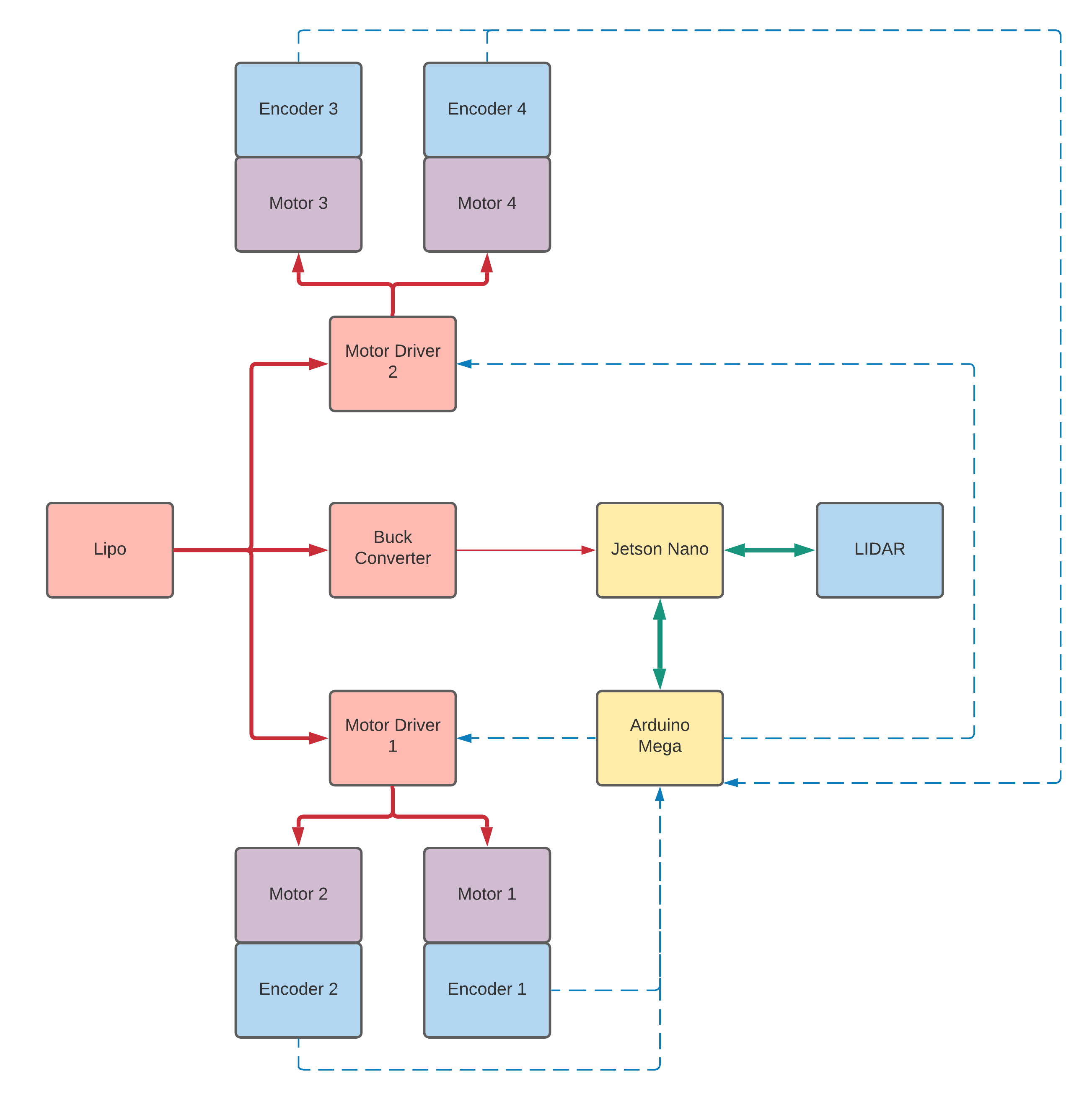
- Solid bi-directional green lines represent lines that transfer both power and data.
- Dark red lines represent 12V power transfer lines
- Light red lines represent 5V power transfer lines
- dashed blue lines represent data transfer lines
- Red squares represnt power supply/distribution components
- Blue squares represent inputs/sensors
- Yellow squares represent computational units
- Purple squares represent output units/actuators.
Results
Preliminary scan data
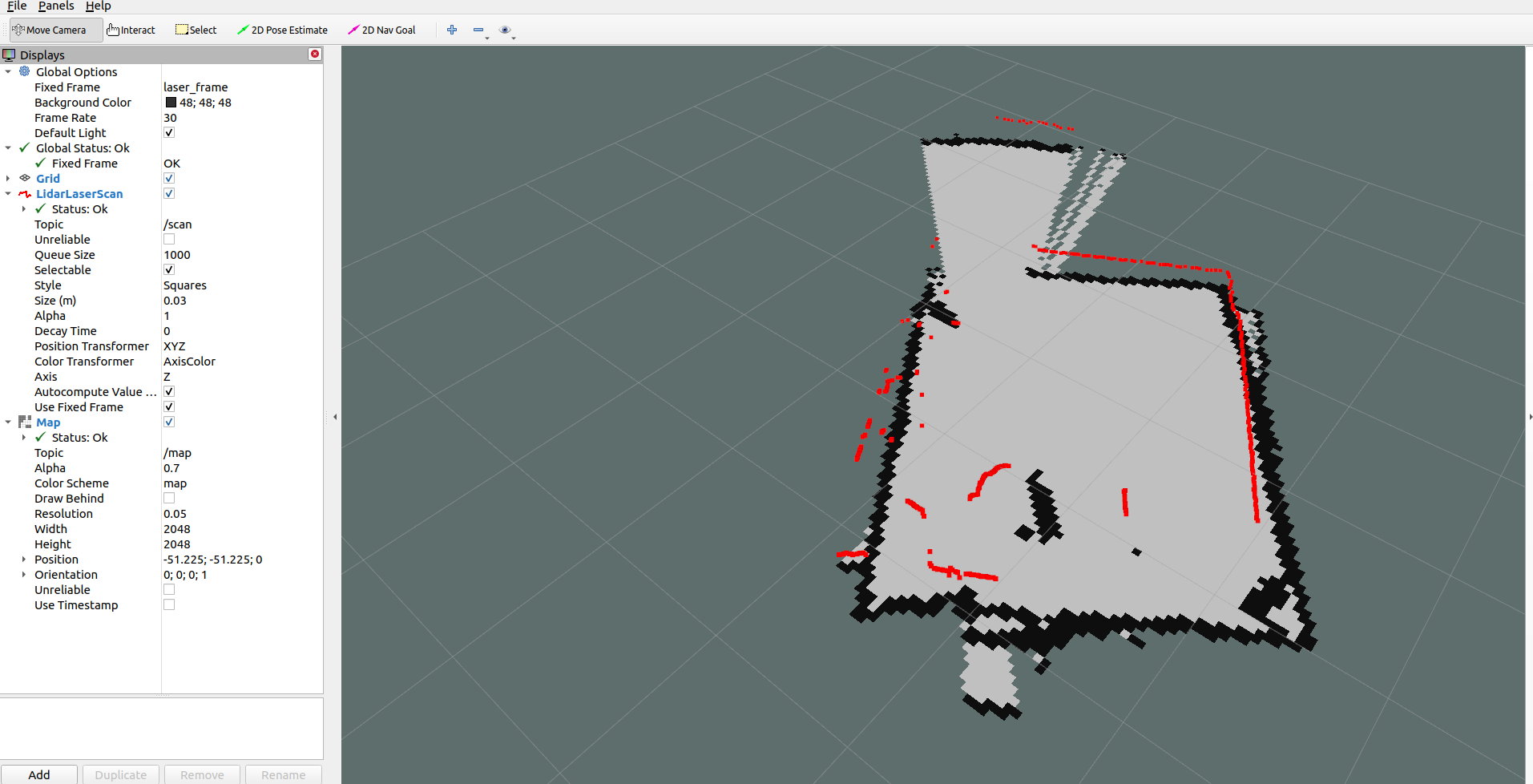
This is an ongoing project, documentation will be updated soon.