
The URDF file format is a way to represent robots and their components in ROS. It uses a modified verion of the XML syntax.
Structure of URDF
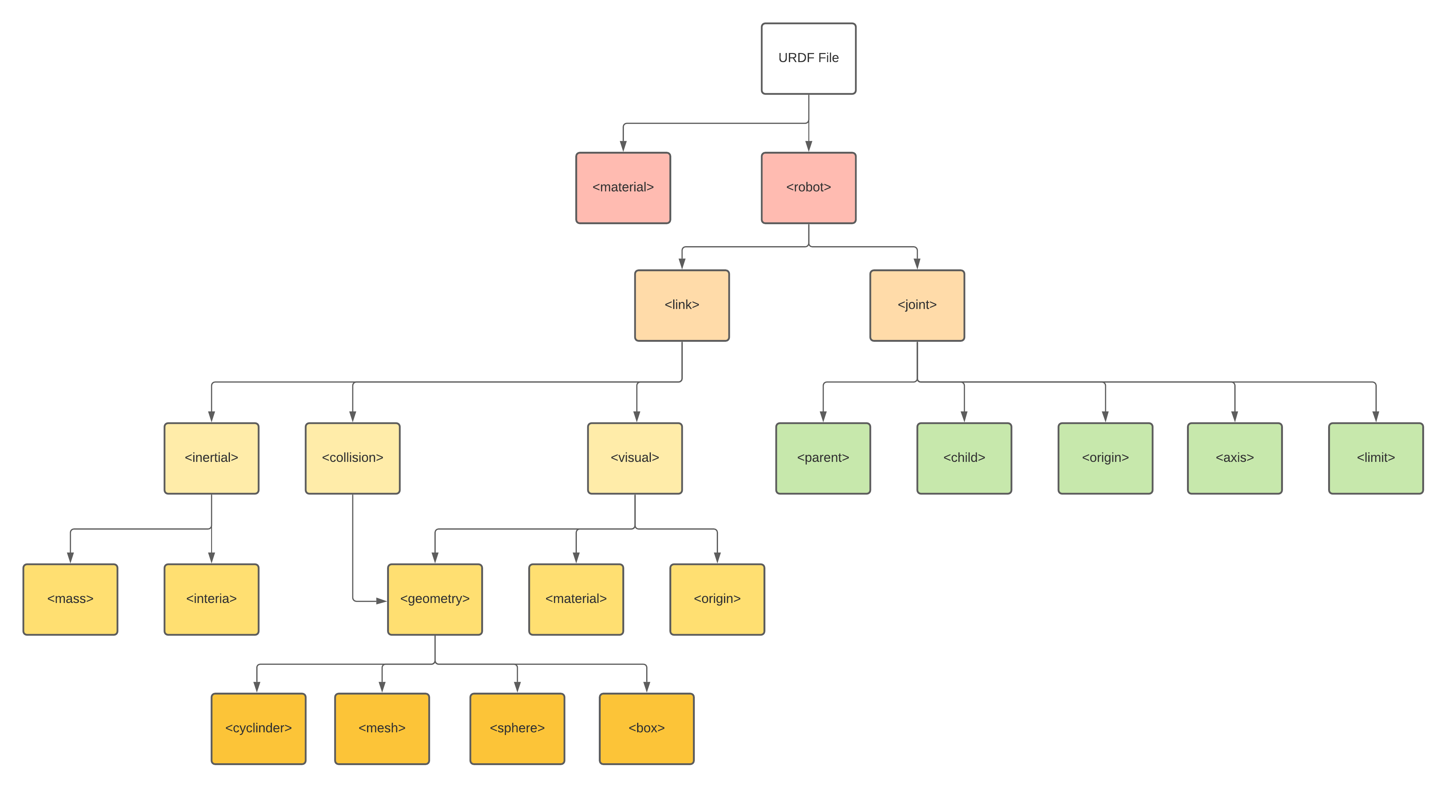
geometry types
box
1
<box size="0.6 0.1 0.2"/>
- size attribute contains the three side lengths of the box. The origin of the box is in its center.
cylinder
1
<cylinder length="0.6" radius="0.2"/>
- Specify the radius and length. The origin of the cylinder is in its center.
sphere
1
<sphere radius="3.0"/>
- Specify the radius. The origin of the sphere is in its center.
mesh
1
<mesh filename="package://robot_description/meshes/base_link_simple.DAE"/>
- A trimesh element specified by a filename, and an optional scale that scales the mesh’s axis-aligned-bounding-box. Any geometry format is acceptable but specific application compatibility is dependent on implementation.
- The recommended format for best texture and color support is Collada .dae files. The mesh file is not transferred between machines referencing the same model. It must be a local file. Prefix the filename with package://
/ to make the path to the mesh file relative to the package . joint types
fixed
1
2
3
4
5
<joint name="base_to_right_leg" type="fixed">
  <parent link="base_link"/>
  <child link="right_leg"/>
  <origin xyz="0 -0.22 0.25"/>
</joint>
continuous
1
2
3
4
5
6
  <joint name="head_swivel" type="continuous">
    <parent link="base_link"/>
    <child link="head"/>
    <axis xyz="0 0 1"/>
    <origin xyz="0 0 0.3"/>
  </joint>
The connection between the body and the head is a continuous joint, meaning that it can take on any angle from negative infinity to positive infinity. The wheels are also modeled like this, so that they can roll in both directions forever.
The only additional information we have to add is the axis of rotation, here specified by an xyz triplet, which specifies a vector around which the head will rotate. Since we want it to go around the z axis, we specify the vector “0 0 1”.
revolute
1
2
3
4
5
6
7
  <joint name="left_gripper_joint" type="revolute">
    <axis xyz="0 0 1"/>
    <limit effort="1000.0" lower="0.0" upper="0.548" velocity="0.5"/>
    <origin rpy="0 0 0" xyz="0.2 0.01 0"/>
    <parent link="gripper_pole"/>
    <child link="left_gripper"/>
  </joint>
Both the right and the left gripper joints are modeled as revolute joints. This means that they rotate in the same way that the continuous joints do, but they have strict limits. Hence, we must include the limit tag specifying the upper and lower limits of the joint (in radians). We also must specify a maximum velocity and effort for this joint but the actual values don’t matter for our purposes here.
prismatic
1
2
3
4
5
6
  <joint name="gripper_extension" type="prismatic">
    <parent link="base_link"/>
    <child link="gripper_pole"/>
    <limit effort="1000.0" lower="-0.38" upper="0" velocity="0.5"/>
    <origin rpy="0 0 0" xyz="0.19 0 0.2"/>
  </joint>
The gripper arm is a different kind of joint, namely a prismatic joint. This means that it moves along an axis, not around it. This translational movement is what allows our robot model to extend and retract its gripper arm.
The limits of the prismatic arm are specified in the same way as a revolute joint, except that the units are meters, not radians.
1
2
3
4
5
6
7
8
9
10
11
12
13
14
15
16
17
18
19
20
21
22
23
24
25
26
27
28
29
30
31
32
33
34
35
36
37
38
39
40
41
42
43
44
45
<?xml version="1.0"?>
<robot name="multipleshapes">
	<link name="dummy">
	</link>
  <link name="base_link">
    <visual>
      <geometry>
        <cylinder length="0.6" radius="0.2"/>
      </geometry>
      <material name="blue">
        <color rgba="0 0 .8 1"/>
      </material>
    </visual>
    <collision>
      <geometry>
        <cylinder length="0.6" radius="0.2"/>
      </geometry>
    </collision>
    <inertial>
      <mass value="10"/>
      <inertia ixx="0.4" ixy="0.0" ixz="0.0" iyy="0.4" iyz="0.0" izz="0.2"/>
    </inertial>
  </link>

  <link name="right_leg">
    <visual>
      <geometry>
        <box size="0.6 0.1 0.2"/>
      </geometry>
      <origin rpy="0 1.57075 0" xyz="0 0 -0.3"/>
    </visual>
  </link>

  <joint name="base_to_right_leg" type="fixed">
    <parent link="base_link"/>
    <child link="right_leg"/>
    <origin xyz="0 -0.22 0.25"/>
  </joint>

  <joint name="dummy_joint" type="fixed">
	 <parent link="dummy"/>
	 <child link="base_link"/>
  </joint>

</robot>
The above code is a modified example from urdf_tutorial package, instructions on how to download the tutorials can be found in the ros urdf wiki.
The output of the above code is as follows:
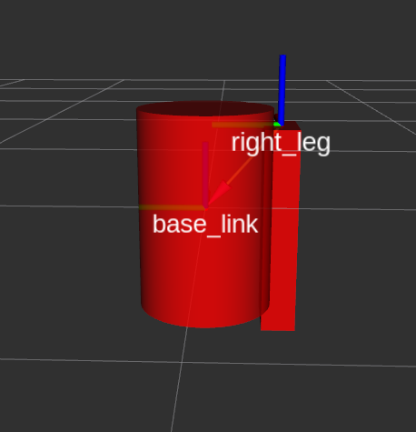
Summary of the above code
- The
fixed frameis the transform frame where the center of the grid is located. Here, it’s a frame defined by our one link,base_link. - The visual element (the
cylinder) has itsoriginat the center of its geometry as a default. Hence, half the cylinder is below the grid. - The
jointis defined in terms of aparentand achild. URDF is ultimately a tree structure with one root link. This means that the leg’s position is dependent on thebase_link’s position. - Let’s start by examining the joint’s
origin. It is defined in terms of the parent’s reference frame. So we are-0.22meters in the y direction (to our left, but to the right relative to the axes) and0.25meters in the z direction (up). This means that theoriginfor the child link will be up and to the right, regardless of the child link’s visualorigintag. Since we didn’t specify arpy(roll pitch yaw) attribute, the child frame will be default have the same orientation as the parent frame. - Now, looking at the leg’s visual
origin, it has both axyzandrpyoffset. This defines where the center of the visual element should be, relative to itsorigin. Since we want the leg to attach at the top, we offset theorigindown by setting the z offset to be-0.3meters. And since we want the long part of the leg to be parallel to the z axis, we rotate the visual part PI/2 around the Y axis. - The collision element is a direct subelement of the link object, at the same level as the visual tag.
- The collision element defines its shape the same way the visual element does, with a geometry tag. The format for the geometry tag is exactly the same here as with the visual.
- You can also specify an origin in the same way as a subelement of the collision tag (as with the visual).
- The
dummylink and joint are added to avoid the following warning given by KDLThe root link base_link has an inertia specified in the URDF, but KDL does not support a root link with an inertia. As a workaround, you can add an extra dummy link to your URDF.
The meshes can be imported in a number of different formats. STL is fairly common, but the engine also supports DAE, which can have its own color data, meaning you don’t have to specify the color/material. Often these are in separate files. These meshes reference the .tif files also in the meshes folder.
Xacro + URDF
The Xacro package can be used to simplify URDF, in paticular it can be used to deal with the following you can use the xacro package to make your life simpler. It does three things that are very helpful.
- Constants
- Simple Math
- Macros
Using Xacro
via .xacro
1
2
<?xml version="1.0"?>
<robot xmlns:xacro="http://www.ros.org/wiki/xacro" name="firefighter">
- At the top of the URDF file, you must specify a namespace in order for the file to parse properly. For example, these are the first two lines of a valid xacro file:
via launch files
1
2
<param name="robot_description"
  command="xacro --inorder '$(find pr2_description)/robots/pr2.urdf.xacro'" />
- You can also automatically generate the urdf in a launch file.
Constants
1
2
3
4
5
6
7
8
9
10
11
12
13
14
15
16
<xacro:property name="width" value="0.2" />
<xacro:property name="bodylen" value="0.6" />

<link name="base_link">
    <visual>
        <geometry>
            <cylinder radius="${width}" length="${bodylen}"/>
        </geometry>
        <material name="blue"/>
    </visual>
    <collision>
        <geometry>
            <cylinder radius="${width}" length="${bodylen}"/>
        </geometry>
    </collision>
</link>
-
The two values are specified in the first two lines. They can be defined just about anywhere (assuming valid XML), at any level, before or after they are used. Usually they go at the top.
-
Instead of specifying the actual radius in the geometry element, we use a dollar sign and curly brackets to signify the value.
1
2
<xacro:property name=”robotname” value=”marvin” />
<link name=”${robotname}s_leg” />
will be read as <link name=”marvins_leg” />
Maths
You can build up arbitrarily complex expressions in the ${} construct using the four basic operations (+,-,*,/), the unary minus, and parenthesis.
1
2
3
<cylinder radius="${wheeldiam/2}" length="0.1"/>
<origin xyz="${reflect*(width+.02)} 0 0.25" />
<box size="${cos(pi/6)}$">
Macros
Simple Macro
The steup
1
2
3
<xacro:macro name="default_origin">
    <origin xyz="0 0 0" rpy="0 0 0"/>
</xacro:macro>
The usage:
1
<xacro:default_origin />
The output:
<origin rpy="0 0 0" xyz="0 0 0"/>
- Every instance of the <xacro:$NAME /> is replaced with the contents of the xacro:macro tag.
- Note that even though its not exactly the same (the two attributes have switched order), the generated XML is equivalent.
- If the xacro with a specified name is not found, it will not be expanded and will NOT generate an error.
Macro with Paramters
The setup:
1
2
3
4
5
6
7
8
9
10
11
12
13
14
15
<xacro:macro name="blue_shape" params="name *shape">
    <link name="${name}">
        <visual>
            <geometry>
                <xacro:insert_block name="shape" />
            </geometry>
            <material name="blue"/>
        </visual>
        <collision>
            <geometry>
                <xacro:insert_block name="shape" />
            </geometry>
        </collision>
    </link>
</xacro:macro>
The usage:
1
2
3
<xacro:blue_shape name="base_link">songs
    <cylinder radius=".42" length=".01" />
</xacro:blue_shape>
The result:
1
2
3
4
5
6
7
8
9
10
11
12
13
    <link name="base_link">
        <visual>
            <geometry>
                <cylinder radius=".42" length=".01" />
            </geometry>
            <material name="blue"/>
        </visual>
        <collision>
            <geometry>
                <cylinder radius=".42" length=".01"/>
            </geometry>
        </collision>
    </link>
- To specify a block parameter, include an asterisk before its parameter name.
- A block can be inserted using the insert_block command
The setup:
1
2
3
4
5
6
7
8
9
10
<xacro:macro name="pr2_caster" params="suffix *origin **content **anothercontent">
  <joint name="caster_${suffix}_joint">
    <axis xyz="0 0 1" />
  </joint>
  <link name="caster_${suffix}">
    <xacro:insert_block name="origin" />
    <xacro:insert_block name="content" />
    <xacro:insert_block name="anothercontent" />
  </link>
</xacro:macro>
The usage:
1
2
3
4
5
6
7
8
9
10
11
12
13
14
<xacro:pr2_caster suffix="front_left">
  <pose xyz="0 1 0" rpy="0 0 0" />
  <container>
    <color name="yellow"/>
    <mass>0.1</mass>
  </container>
  <another>
    <inertial>
      <origin xyz="0 0 0.5" rpy="0 0 0"/>
      <mass value="1"/>
      <inertia ixx="100"  ixy="0"  ixz="0" iyy="100" iyz="0" izz="100" />
    </inertial>
  </another>
</xacro:pr2_caster>
The result:
1
2
3
4
5
6
7
8
9
10
11
12
13
<joint name="caster_front_left_joint">
  <axis xyz="0 0 1" />
</joint>
<link name="caster_front_left">
  <pose xyz="0 1 0" rpy="0 0 0" />
  <color name="yellow" />
  <mass>0.1</mass>
  <inertial>
    <origin xyz="0 0 0.5" rpy="0 0 0"/>
    <mass value="1"/>
    <inertia ixx="100"  ixy="0"  ixz="0" iyy="100" iyz="0" izz="100" />
  </inertial>
</link>
ROS Control
Coming soon…