Port Manipulation refers to the technique of directly working with the underlying registers of the ATmega chip(in this context) instead of relying on predefined Arduino functions. This is primarily done to reduce your code’s memory footprint and make it run faster.
To understand how the memory and speed get affected by using the Arduino functions, lets take an example,
Here is the code for the arduino pinMode() function:
1
2
3
4
5
6
7
8
9
10
11
12
13
14
15
16
17
18
19
20
21
22
23
24
25
26
27
28
29
30
31
void pinMode(uint8_t pin, uint8_t mode)
{
        uint8_t bit = digitalPinToBitMask(pin);
        uint8_t port = digitalPinToPort(pin);
        volatile uint8_t *reg, *out;

        if (port == NOT_A_PIN) return;

        // JWS: can I let the optimizer do this?
        reg = portModeRegister(port);
        out = portOutputRegister(port);

        if (mode == INPUT) {
                uint8_t oldSREG = SREG;
                cli();
                *reg &= ~bit;
                *out &= ~bit;
                SREG = oldSREG;
        } else if (mode == INPUT_PULLUP) {
                uint8_t oldSREG = SREG;
                cli();
                *reg &= ~bit;
                *out |= bit;
                SREG = oldSREG;
        } else {
                uint8_t oldSREG = SREG;
                cli();
                *reg |= bit;
                SREG = oldSREG;
        }
}
As you can see, although we tend to treat it as a single line of code, internally, it contains many lines of code, and multiple function calls to get its job done. This article will learn how to write into registers directly and further understand that pinMode and other stock functions internally do the same.
Before starting port manipulation, you need to get yourself familiar with bit math and bit manipulation; here is a quick intro to it.
Bit Manipulation
Manipulating the internal registers of the ATmega chip involves flipping bits in 8-bit (usually) arrays, as the ATmega328p is 8-bit in nature, so our primary learning objective would be to learn how to flip, read, write to bit/bits without affecting or disturbing the other bits in a given array.
Setting a bit HIGH
Let us learn how to set a bit HIGH/1 in a given array. For this example let us consider the following. You are given an 8-bit array and you do not know the states of any of the pins, you are further required to turn the 4th bit in the array to 1. (irrespective of its current state)
Given array :: xxxx yxxx Create an array :: 0000 1000 (can be done using 1«3) Perform OR operation on both the arrays. Resulting array :: xxxx 1xxx
As we can see, irrespective of the initial state of the 4th bit, it is now set to 1 for sure. Also, notice how the other 7 bits remain unaffected by this operation regardless of their initial state.
To put this up as a syntax, assuming the given array is called EXP. The above logic can be written as
1
2
EXP = EXP | (1<<3); //One way to write it
EXP |= (1<<3); //A more compact way of writing the same expression.
Setting a bit LOW
Setting a bit LOW/0 is pretty much similar to setting a bit HIGH/1 in terms of our approach. Let us consider an example to understand better. You are given an 8-bit array, and the initial states of all the pins are unknown. We have to set the 4th bit in the given array to 0. (irrespective of its current state)
Given array :: xxxx yxxx Create an array :: 0000 1000 (can be done using 1«3) Invert the array :: 1111 0111 (can be done using ~(1«3) ) Perform AND operation on the inverted array and the given array. Resulting array :: xxxx 0xxx
Just like we saw in the previous example of setting a bit HIGH, only the 4th bit is set to 0, and all the other pins are left unaffected irrespective of their initial states. To put this in syntax, assuming the given array is called EXP. The above logic can be written as
1
2
EXP = EXP & ~(1<<3); //One way to write it
EXP &= ~(1<<3); //A more compact way of writing the same expression.
Reading the state of a bit
Just like setting the setting a bit HIGH and LOW, we might at times want to read the current state of the bit. Let us consider the following example. You are given an 8-bit array, and the initial states of the bits are unknown. We have to find the current state of the 4th bit in the given array.
Given array :: xxxx yxxx Left shift the given array :: 000x xxxy (such that y is at the corner, can be done using EXP»3 ) Perform AND operation with the shifted array and 0000 0001. Resulting array :: 0000 000y
The above logic can be written as,
1
RESULT = EXP>>3 & 1;
Flipping the state of a bit
Sometimes especially in loops, we might just need to flip the state of a bit over and over again without bothering about its initial or final states. For example let us consider an 8-bit array where we are supposed to flip the state of the 4th bit.
Given array :: xxxx yxxx Create an array :: 0000 1000 (can be created using 1«3 ) Perform XOR Operation on the two arrays. Resulting array :: xxxx (~y)xxx
The above logic can be written as,
1
2
EXP = EXP ^ (1<<3); //One way to write it
EXP ^= (1<<3); //A more compact way of writing the same expression
Port Registers
Port registers allow for faster manipulation of the I/O pins, the predefined functions for GPIO in Arduino, while easy to use, conceal a lot of the features and functionality the ATmega can offer.
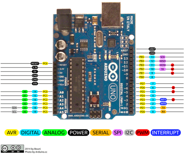
The ATmega 328p has three ports, refer to the yellow tag markers in the below picture for the labels.
Port B – Digital pins 8 to 13 Port C – Analog Pins Port D – Digital pins 0 to 7
What are ports ?
Ports are collections of Pins sharing a set of common SFR’s. (vaguely speaking, a group of pins is called a port)
To intuitively understand the need for port registers, let’s quickly list all the attributes a GPIO pin can have in general.
- INPUT / OUTPUT / INPUT_PULLUP – PinMode()
- HIGH / LOW – DigitalWrite()
- “Value the pin stores” – DigitalRead()
Each of these attributes have one register associated for them, they are defined as the following.
- Data Direction Register (DDR) – INPUT / OUTPUT
- Data Register (PORT) – HIGH / LOW
- Input Pin Register (PIN) – “value the pin stores”
NOTE: AnalogRead() and AnalogWrite() have separate registers and will be discussed in ADC and timers posts.
The DDR register, determines whether the pin is an INPUT or OUTPUT. The PORT register controls whether the pin is HIGH or LOW, and the PIN register reads the state of INPUT pins set to input with pinMode(). DDR and PORT registers may be both written to, and read. PIN registers correspond to the state of inputs and may only be read.
Each bit of these registers corresponds to a single pin; e.g. the low bit of DDRB, PORTB, and PINB refers to pin PB0 (digital pin 8).
Let us look at some examples on how to use these registers.
1
2
3
4
5
6
7
8
9
10
11
// LED Blinking Code
void setup(){
  DDRB |= 1<<6; //pinMode(13,OUTPUT);
}

void loop(){
  PORTB |= (1<<5); //digitalWrite(13,HIGH);
  delay(1000);
  PORTB &= ~(1<<5); //digitalWrite(13,LOW);
  delay(1000);
}
Note that the entire code block in void loop can be replaced by the following code:
1
2
3
4
void loop(){
  PORTB ^= (1<<5);
  delay(1000);
}
Note that the code DDRB |= 00101110; is the equivalent of setting the pins 8, 12 as inputs and 9,10,11,13 as outputs, this would have taken 6 pinMode function calls to achieve, similarly other tasks like setting multiple pins HIGH or LOW or reading the sates of the pins can be achieved in fewer lines of code.
PIN register reads the data from all the pins at once, and can be used like the other registers shown in the above examples. More examples will be taken up in the subsequent tutorials.
As a concluding example let us take up the following code.
1
2
3
4
5
6
7
8
9
10
11
12
13
14
15
16
17
18
19
20
21
22
23
24
25
26
27
28
29
30
31
32
33
34
35
36
37
38
39
40
41
42
43
44
45
46
47
48
49
50
51
52
53
54
55
56
57
/*
Objective : The void loop is busy with a process
shown as delay(5000). You need the AVR to perform some smaller
and more important tasks once in a while.
*/
/*
volatile int state = LOW;
const int led = 12;
const int button = 2;
void setup(){
  pinMode(led, OUTPUT);
  pinMode(button,INPUT_PULLUP);
  attachInterrupt(digitalPinToInterrupt(button),blinker,FALLING);
}
void blinker(){

  state = state == HIGH ? LOW : HIGH;
  digitalWrite(led,state);
}
void loop()
{
 delay(5000);
}
*/

/*--------------------------------------------------*/

ISR(INT0_vect)
{
  PORTB ^= (1 << 4);
}

void setup()
{

  //Enable D12 as OUTPUT
  DDRB |= (1 << 4);
  //Enable D2 as INPUT_PULLUP
  DDRD &= ~(1 << 2);
  PORTD |= (1 << 2);

  //Enable Falling edge
  EICRA = 0;
  EICRA |= (1 << ISC01);
  //Enable Mask
  EIMSK = 0;
  EIMSK |= (1 << INT0);
  //Enable global interrupts
  sei();

  // put your setup code here, to run once:
}
void loop()
{
  delay(5000);
  // put your main code here, to run repeatedly:
}
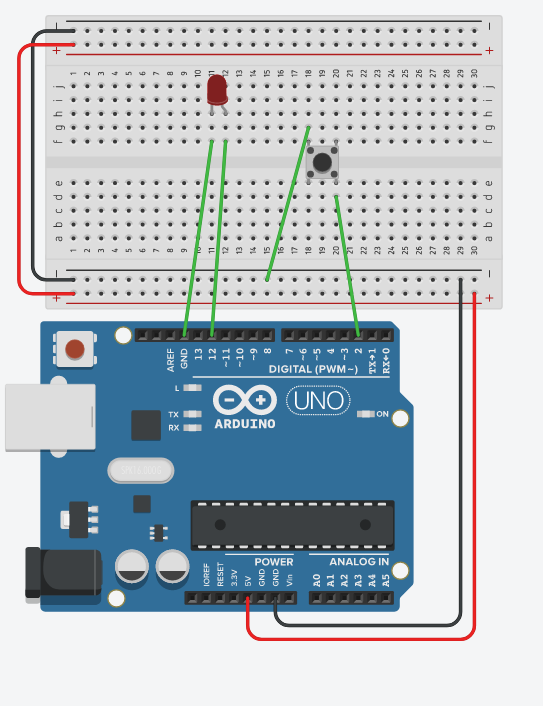
The schematic for the above code is attached below. While the code might contain a few new topics like interrupts, it is well documented and understandable. We will dive into the interrupts part in the following tutorial.