
The primary objective of this project was to build an underwater rover platform that can be used to experiment with topics ranging from control systems and computer vision to embedded systems and machine learning.
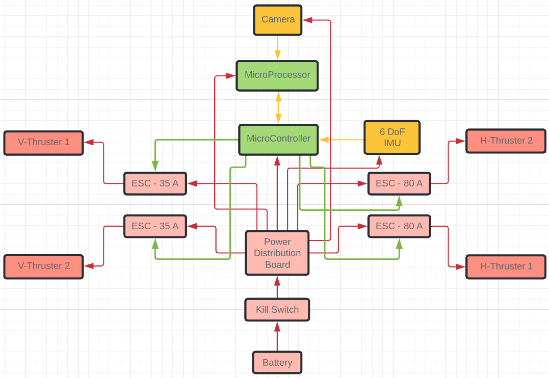
Hardware Layout
Fabrication
Test Stand
The test stand is used to measure the thrust that was generated by different combinations of motors and propellers. Devices that measure thrust are already available in the market, but they are meant for measuring the thrust of propellers designed to work in the air. Our design is based on these devices that work in air, and was modified so that the electronics can be placed outside the water, while the propeller and the motors are inside water.
The device works on the principle of moments. It consists of an arm that is pivoted near one end. This end has an extension that makes contact with a load cell that measures the thrust. The other end of the arm is attached to the motor fitted with the propeller, and is dipped inside water. As the motor rotates, the propeller generates thrust and pulls the arm in the forward direction, which results in a clockwise moment about the pivot point. This moment is balanced by the anticlockwise moment that is generated by the normal force of the load cell on the other end. This force is measured by the load cell and is adjusted according to the arm lengths on either side of the pivot to give the final reading of the thrust generated by the propeller.
The load cell needs to be calibrated before every test in order to remove the weight of the arm from interfering with the readings. The parameters of the load cell were set in such a way that it gives a precision of upto 1gf.
Two prototypes of the test stand were built and tested.
Prototype 1
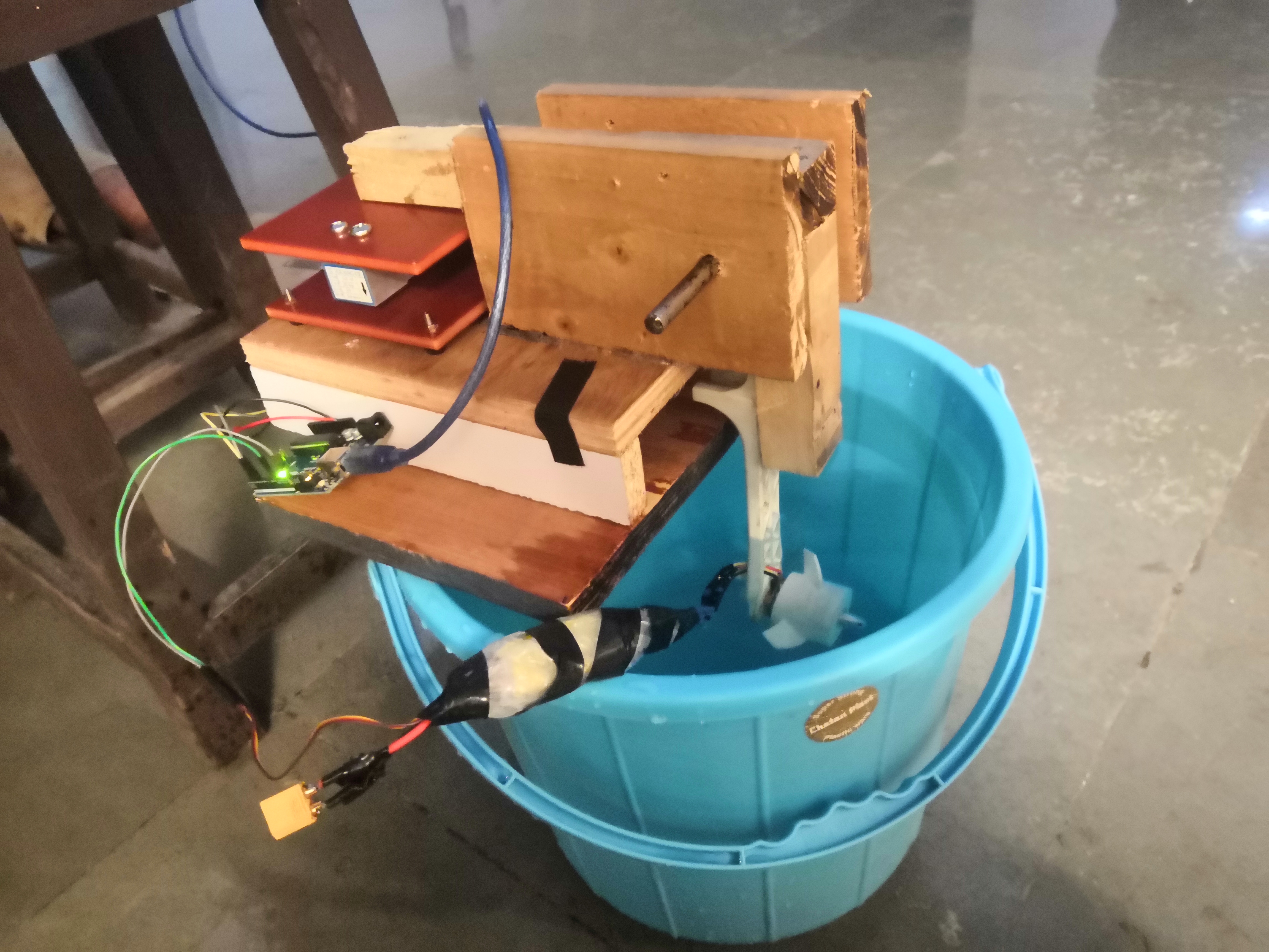
This is a makeshift prototype which was built using pieces of wood and the broken arm of a quadcopter. The motor was dipped in a bucket of water to measure the thrust.
Limitations:
- As the arm lengths were very small, the motor could not be tested at greater depths.
- Since the setup was limited to testing in a bucket of water, the readings of the thrust were not fully accurate because propellers create turbulence when water hits the walls of the bucket.
- The arms were made of wood, which could very easily get spoiled in water. Propellers of larger thrust could also break the arms apart.
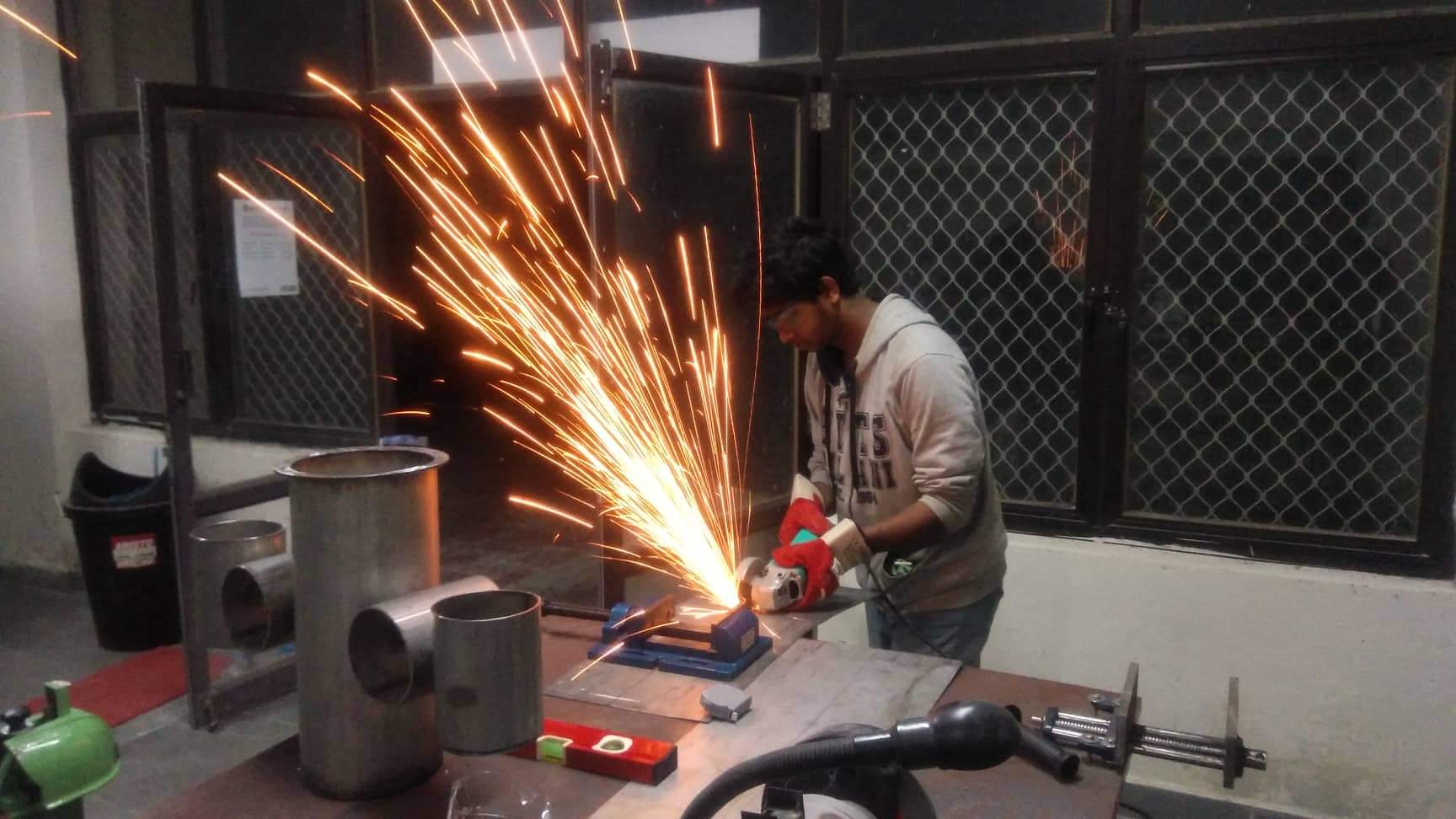
Prototype 2
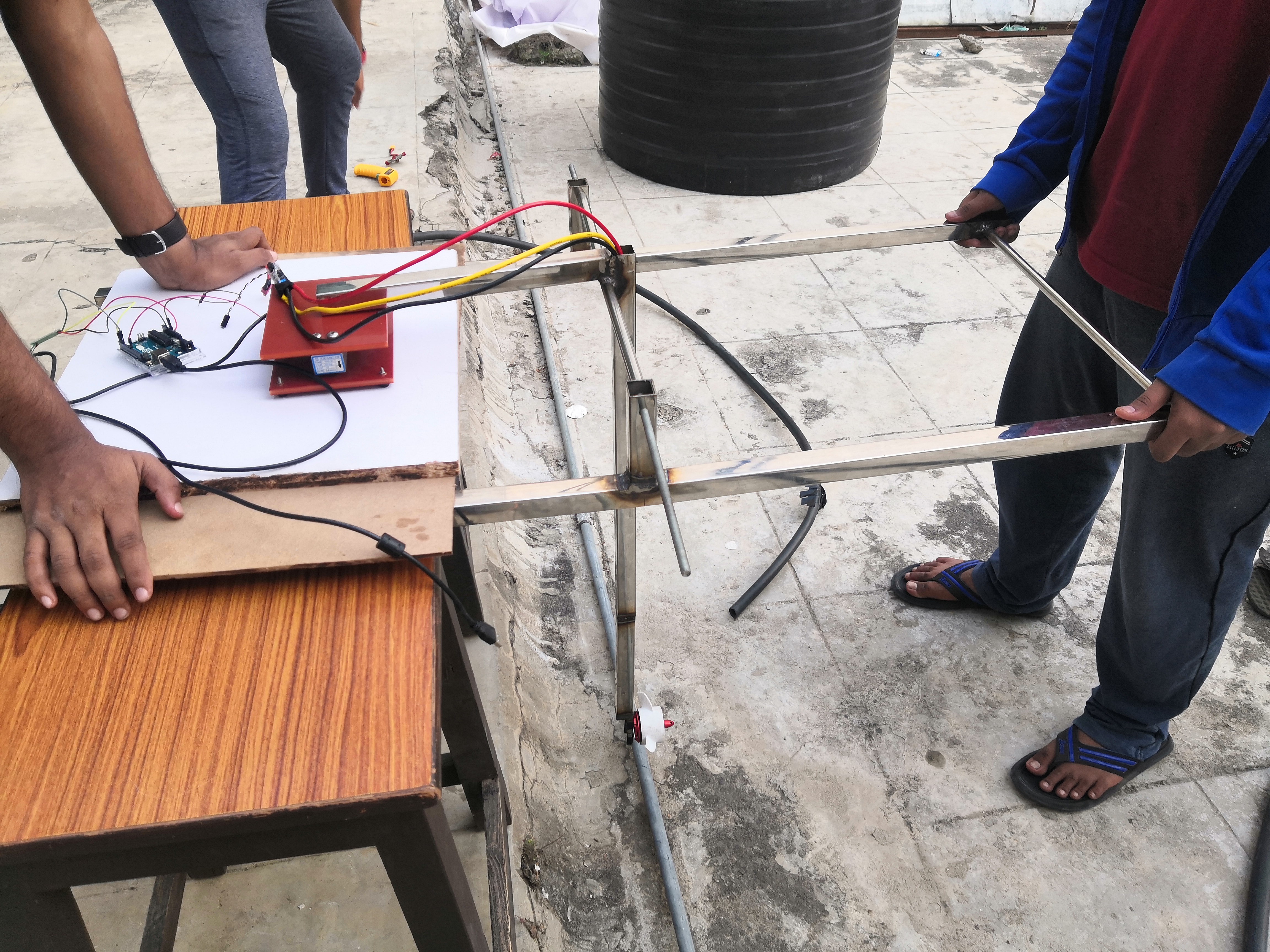
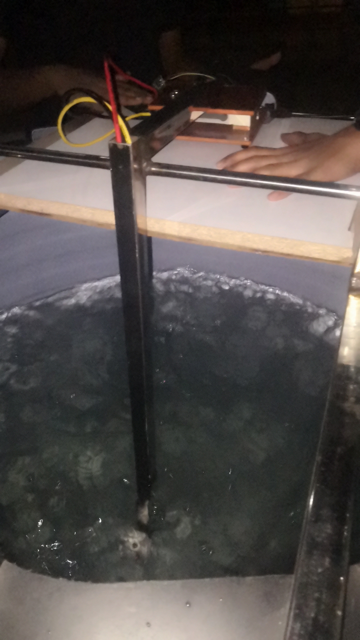
This is the model that was used for all the final testing. The arms and frame are both made of stainless steel extrusions that were welded together in the workshop. The frame was then used along with a 1000 litre water tank.
Limitations
- Since the arms were also made of stainless steel, they were heavy and could interfere with the readings. This was taken into account in the calibration phase of the load cell.
Advantages
- The bigger tank ensured that there was no turbulence due to water hitting the walls of the vessel.
- Since the arm was made of stainless steel, it was much more durable, and could be tested with all possible combinations of motors and propellers.
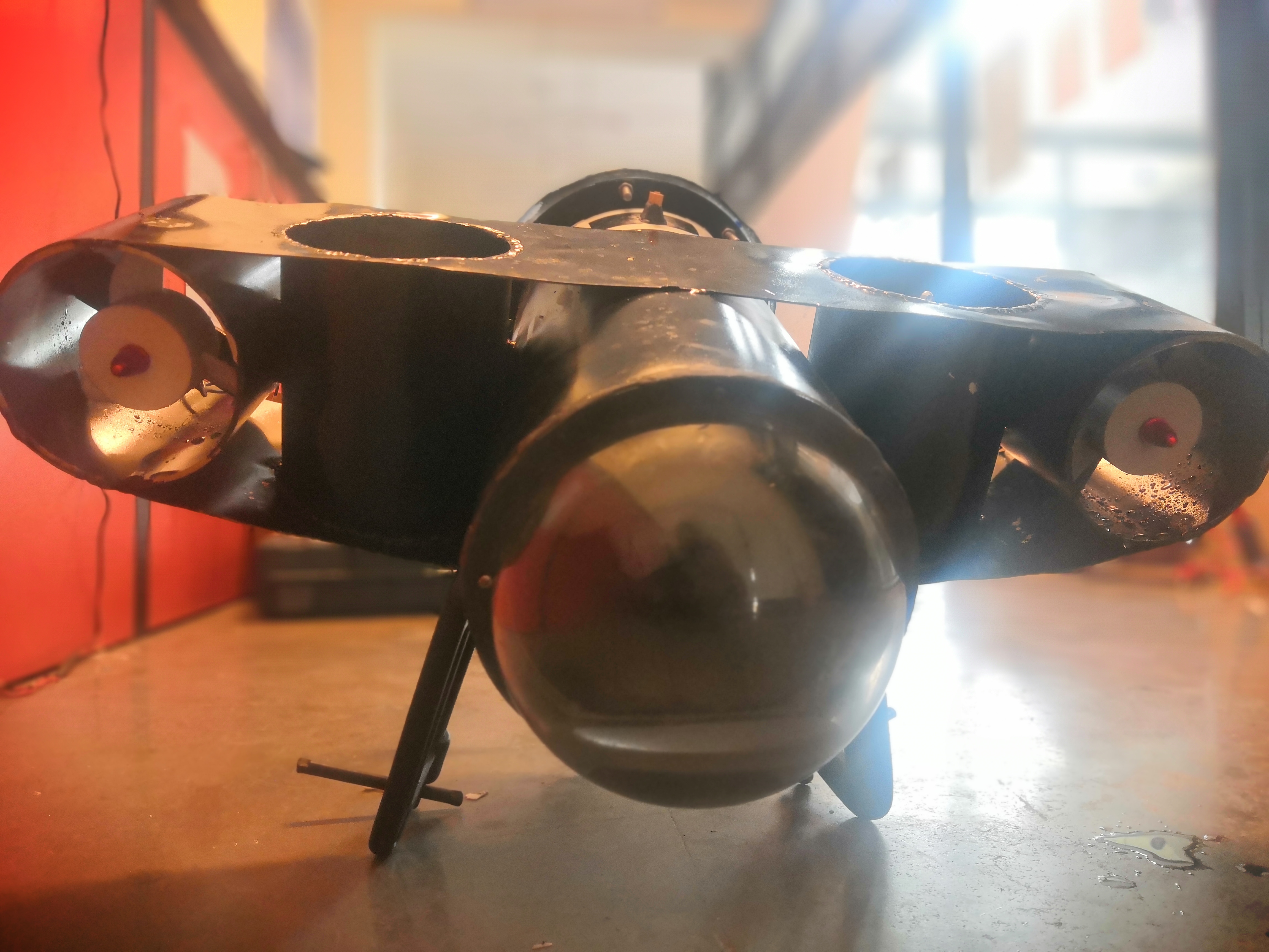
Rover
After all possible combinations of motors and propellers were tested to get the best possible thrust, the actual rover was fabricated. The thrust values were important to be calculated before fabricating the rover since the amount of upward thrust required for the rover to stay at a particular height needed to be known so that the rover could be designed to be positively buoyant if necessary.
The main parts of the rover can be listed as:
-
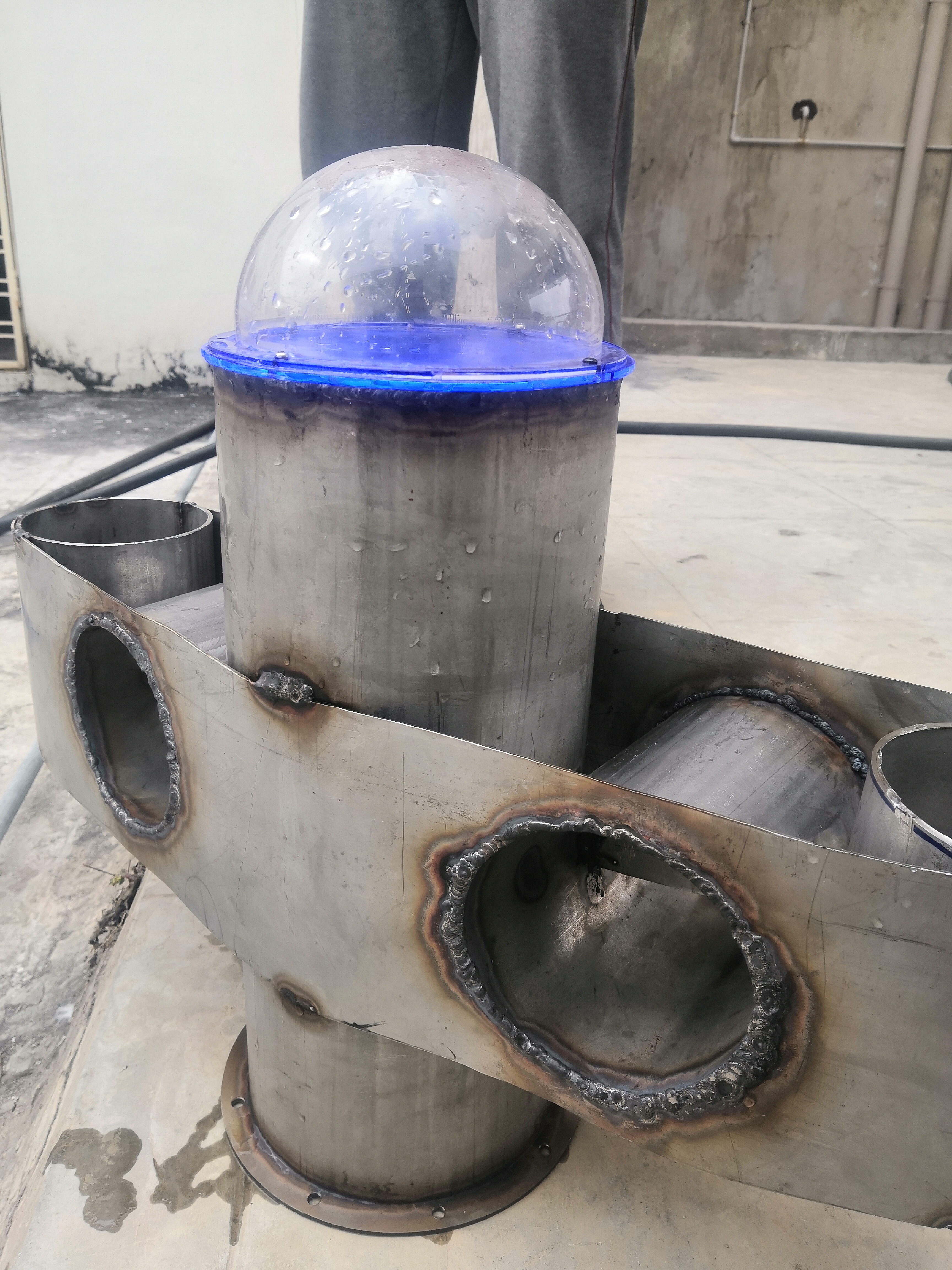
Central enclosure: This is the single cylindrical enclosure in the centre of the rover, that houses all the electrical components, the power system and the control system. It is made up of a thick stainless steel tube, with a diameter that is sufficiently large to fit in the single board computer (Raspberry Pi 4 or Jetson Nano) along with the LiPo battery back comfortably.
-
Front dome: This is the clear dome made of acrylic in the front of the rover. It will be used to house the camera in the future prototypes. Its shape ensures the maximum possible field of view for the camera. This was fixed permanently to the central enclosure using clay epoxy, in order to make the joint waterproof.
-
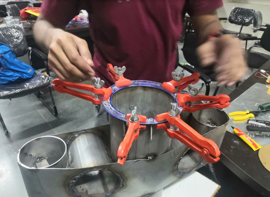
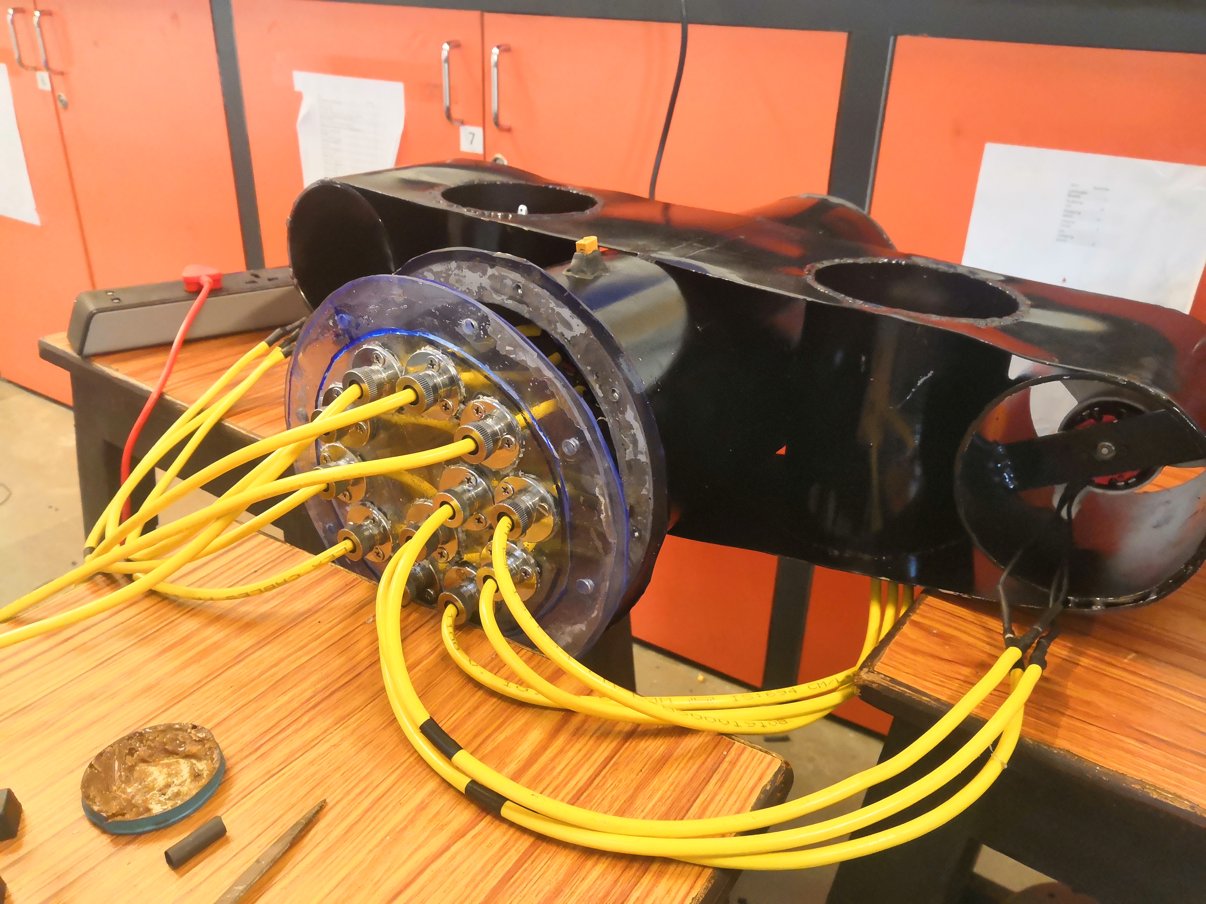
Backplate: This is the clear plate at the back of the rover. It houses the valves that were used to connect the cables from the thrusters to the power distribution inside the central enclosure. These valves were permanently fixed to the plate to ensure no leakage of water from the joints. The plate is fixed to the central enclosure using a set of 12 bolts and nuts. Since this plate was made to be removable, its waterproofing was of utmost importance. We made a custom seal for the backplate using a soft acrylic sheet. Furthermore, we used silicone sealant before fastening the bolts to ensure the best possible waterproofing of the joint.
-
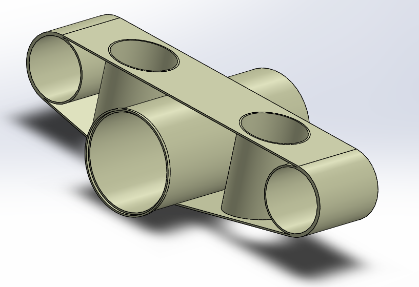
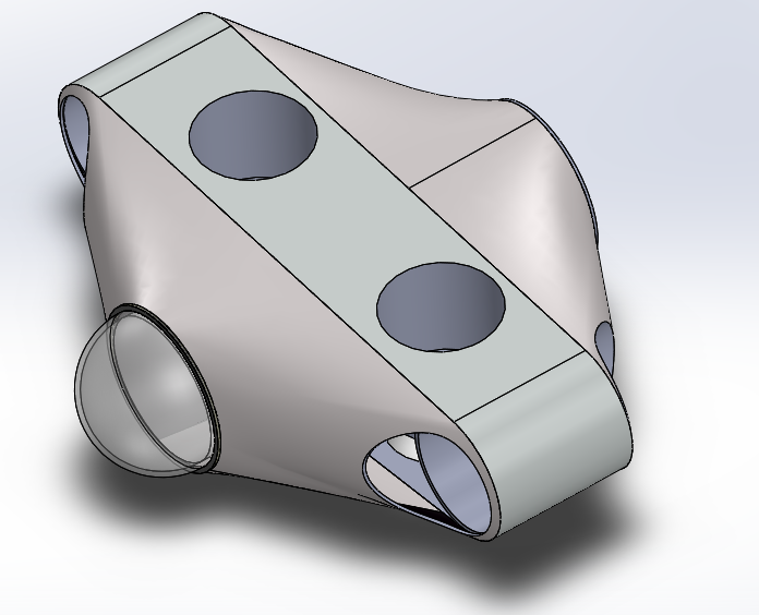
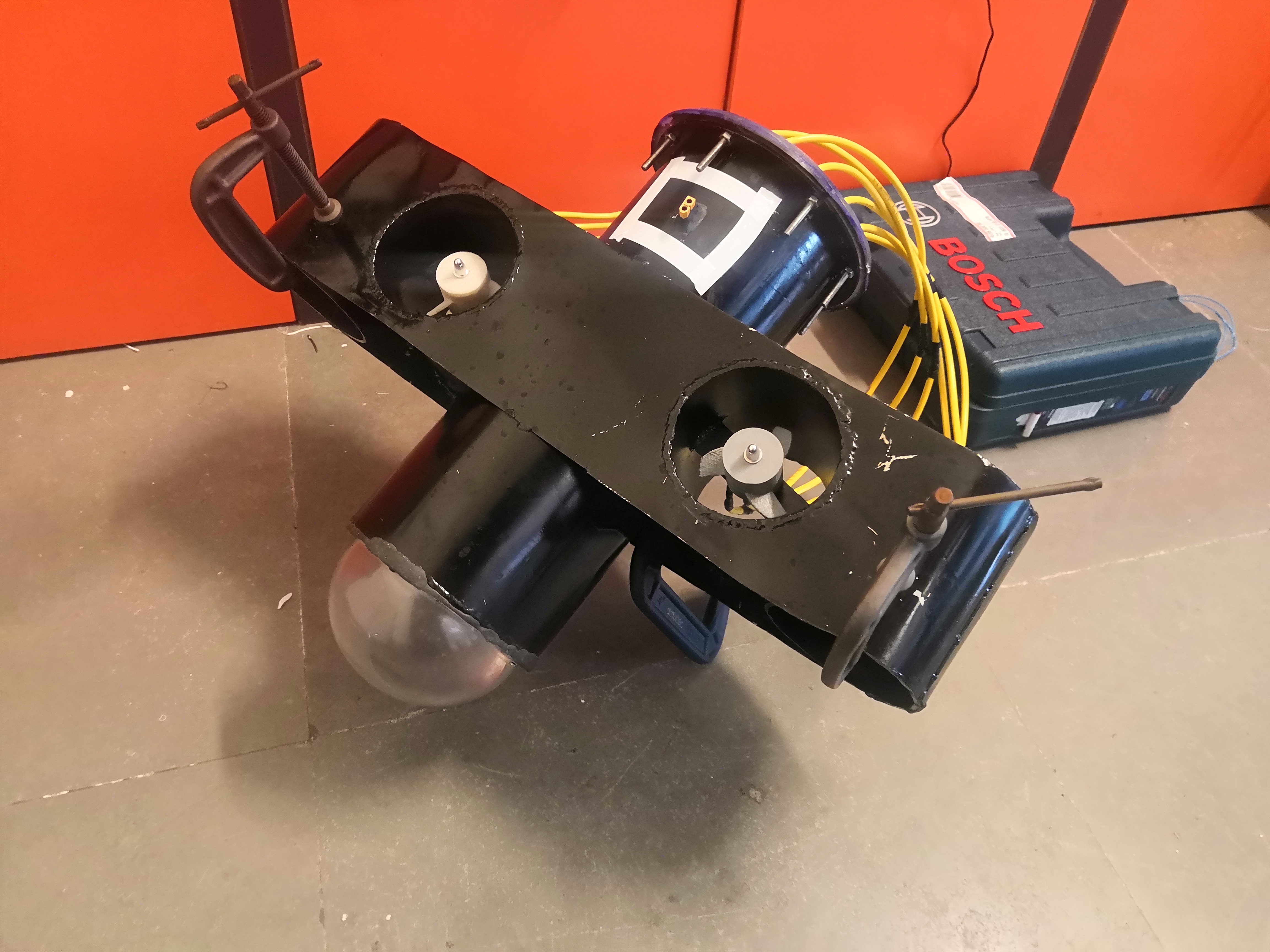
Thruster shrouds: These are the four tubes that enclose the mounts for the thrusters. The configuration of thrusters on our rover are:
- Two thrusters facing in the horizontal direction on the far ends of both the sides.
- Two thrusters facing the vertical direction adjacent to the central enclosure, on both sides.
These shrouds help in increasing the thrust that was generated by the thrusters while simultaneously protecting them from hitting large objects underwater. They are also made out of thick stainless steel cylindrical tubes.
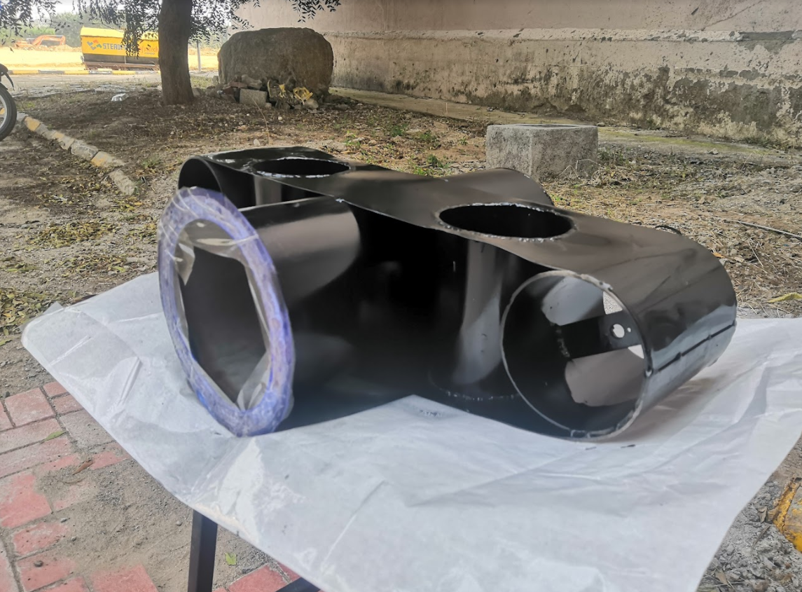
We also attached a thin sheet of stainless steel to join the shrouds from end to end in order to give the design a more streamlined look, as well as to increase the surface area of the rover, which helped in increasing the buoyant force acting on it.
- Emergency stop: This component is incorporated into the top of the central enclosure so that it is easy to access. It is designed like a ‘key’ which when detached from the bot will cut off power to all the components of the bot.
The entire rover was fabricated in the central workshop. Stainless steel tubes were cut and welded together in order to first make the basic frame of the bot. Mounts for the thrusters were also welded in place.
Next, the dome and backplate along with the valves were attached.
Finally, the sheet covering the thruster shrouds was welded and the bot was painted black to give it a finishing touch.
Propulsion
Motors
Brushless DC motors have been chosen for the project as they are the most ideal choice of actuators for high speed and high torque applications. Unlike typical DC motors which are carbon brushes for commutation, BLDC motors have zero contact points which therefore allows them to obtain high speeds and also incur less maintenance. After testing out various BLDC motors in the thruster test stand we decided to go ahead with 400 kv and 1000 kv motors for vertical and horizontal thrusters respectively. These motors, unlike traditional ones, need specialised driving circuits called “Electronic Speed Controllers” for controlling them. We went ahead with 80A and 35A ESC’s for the 400kv and 1000kv motors based on their power consumption.
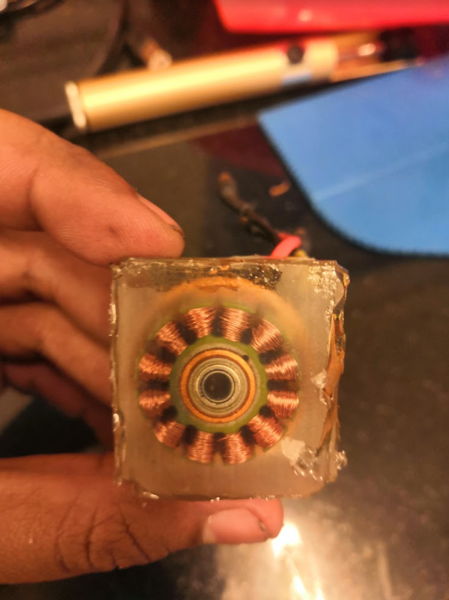
Most of the commercially available BLDC motors are meant for usage in air and not water due to which we had to prepare the motors before using them for our project. While we have observed that dipping a BLDC underwater as it is doesn’t cause any problems and the motor works normally. It is well documented that prolonged usage underwater causes corrosion of the chemical coating on the stator coils that once depleted causes internal shorting and therefore drastically reduces performance before permanently killing the motor.
We went ahead with a 2 part epoxy resin that was applied on top of the stator coils so that they do not come in contact with the water, special care was taken to select the resin as thermal conductivity and water resistance were two important factors for our use case. The stators were coated in epoxy and left to cure overnight, the results were promising and there was no noticeable difference in the amount of thrust produced although we did see the lifetime of the motors increase drastically.
The curing process, although working, can be made better by using vacuum to remove air pockets that were generated during the epoxy mixing process.
Propellers
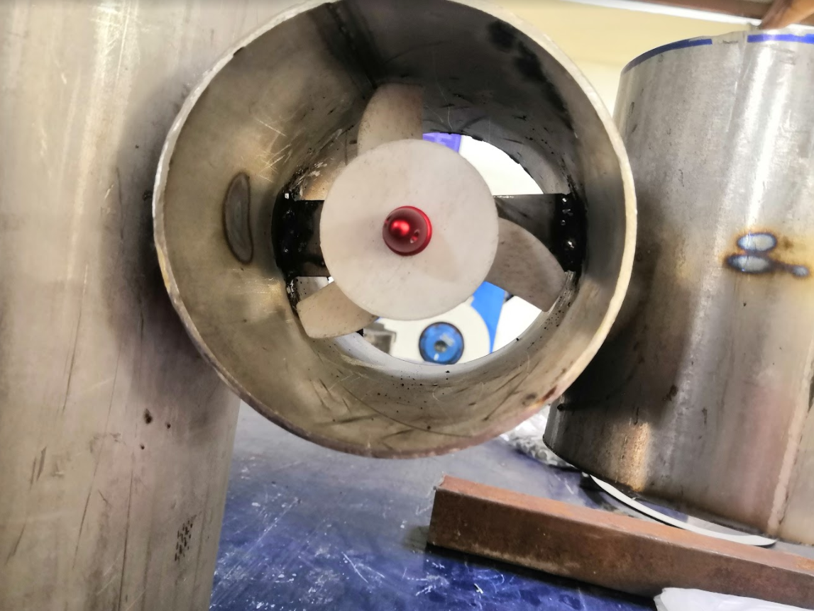
Custom propellers were designed for the BLDC motors using MATLAB, Solidworks and OpenProp ( an open source software used for the design and analysis of marine propellers). Given that the propellers were 3D printed in sandboxx using PLA filament. The propellers were designed for easy and fast fabrication due to which they were of fixed pitch. Two different propellers were created as the motor housing diameters for the 1000kv and 400kv motors were very different.
Each propeller model once generated in MATLAB was exported into solidworks as a set of splines and the final model was formed via extrusion and shape forming.
Testing
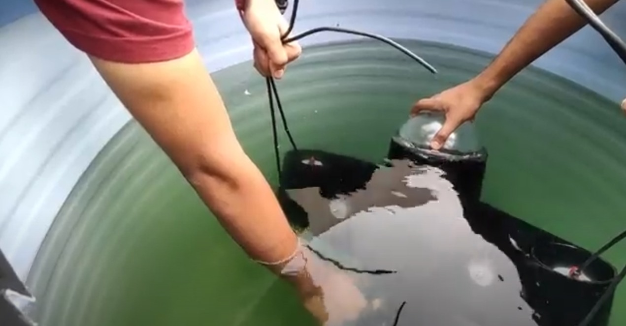
Multiple subsystems of the rover were tested individually many times before the final assembly took place, given that the team had no access to a proper swimming pool. Initial testing took place in any available container ranging from a water bucket to 1000 L PVC Tank that we custom cut out for the project. The final testing for the robot took place in a pool outside of the campus, we had a limited set of tools at hand given the location and shortage of crew. The final test did show a few problems but they were not major enough and the rover did function as per expectations.
Upcoming Work
The current rover design has many shortcomings and given that it was the first prototype we were working on, the focus was more on testing the feasibility of the idea and getting to know what it takes to get a rover working rather than actually making a full fledged model. That being said the team is currently working on a revised prototype that addresses most if not all of the shortcomings in the first model. Since the campus now has a swimming pool we believe that the testing and debugging will be very easy when compared to the past. Given the remote setting since last semester the team has been working on the simulation and software side of the rover.